background image

19

Same Level

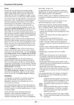
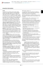
B-Out Waveform

JW130

11

TUNER

17

L103

IC101

RV101

A

A Board component side

25" 2.21V +/- 0.01V
29" 2.52V +/- 0.01V

R - out Waveform

SUB BRIGHTNESS ADJUSTMENT

1.

Input a Phillips colour pattern.

2.

Press ‘TEST’ ‘TEST’ 13 on the Remote Commander.

3.

Adjust the ‘Sub-Brightness’ data so that there is barely a 
difference between the 0 IRE and 10 IRE signal levels.

SUB CONTRAST ADJUSTMENT

1.

Input a video signal that contains a small 100% white area on a 
black background 

2.

Set the picture control to maximum. [‘TT01’]

3.

Connect an oscilloscope to Pin 1 of CN504 [A Board].

4.

Enter into the ‘Picture’ service menu.

5.

Adjust the ‘R - Drive’ data to obtain the following waveform.

SUB COLOUR ADJUSTMENT

1.

Receive a PAL colour bar signal.

2.

Connect an oscilloscope to Pin 3 of CN504 [A Board].

3.

Enter into the ‘Picture’ service menu.

4.

Adjust the ‘Sub Colour’ data so that the Cyan, Magenta and 
Blue colour bars are of equal levels as indicated below.

Note: Ensure that no signal is applied to the Antenna socket while 

carrying out the following IF adjustments.

SYSTEM B/G, D/K, I & L I.F ADJUSTMENT

1.

Input a 38.9Mhz carrier signal at 100dBuV to Pin 11 [IF 
output] of the tuner [TU101].

2.

Measure the voltage at Pin 17 of [IC101].

3.

Adjust L103 [A Board] to obtain a voltage of 2.5V +/- 0.3V.

SYSTEM L BAND 1 I.F ADJUSTMENT

1.

Input a 34.0MHz carrier signal at 100dBuV to Pin 11 [IF 
output] of the tuner [TU101].

2.

Select ‘system L’ + C00 [channel 00].

3.

Measure the voltage at Pin 17 [IC101].

4.

Adjust RV101 [A Board] to obtain a voltage of 2.5V +/- 0.3V.

TUNER AGC ADJUSTMENT

1.

Receive a signal of 65dBuV / 75 ohm terminated, via the tuner 
antenna socket.

2.

Connect a voltmeter to JW130 [A Board].

3.

Enter into the ‘Test Menu’. 

4.

Select the ‘AGC Adjust’ menu item.

5.

Adjust the data using the Yellow and Green buttons on the 
Remote Commander to obtain a voltage of 3.0V +/- 0.2V.

TECHNICAL

GD - Secam

30

BD - Secam

31

RC - Secam

11

GC - Secam

19

BC - Secam

10

GD - Sports 

30

BD - Sports 

36

RC - Sports 

14

GC - Sports 

15

BC - Sports 

17

Y - Delay (AV)

07

Содержание TRINITRON KV-21M5D

Страница 1: ...MMANDER DEST CHASSIS NO SELF DIAGNOSTIC FUNCTION KV 21M5D RM 883 AEP SCC Q04M A KV 21T5D RM 883 AEP SCC Q04N A KV 21M5K RM 883 OIRT SCC Q03V A KV 21T5K RM 883 OIRT SCC Q03X A KV 21T5R RM 883 OIRT SCC Q03W A TRINITRON COLOR TV M I C R O F I L M Layer 1 RM 883 PROGR MENU N ...

Страница 2: ...nals REAR 21 pin Euro connector CENELEC standard Inputs for Audio and Video signals Inputs for RGB Outputs of TV Video and Audio signals FRONT Video input phono jack Audio inputs phono jacks Headphone jacks minijack Sound output 2 x 4 5W Music Power Power requirements 220 240V Dimensions Approx 598x456x467mm Weight Approx 21kg Supplied accessories RM 883 Remote Commander 1 IEC designated R6 batter...

Страница 3: ...Box OFF OFF OFF Scart 1 ON ON ON Scart 2 OFF OFF OFF Front in 3 ON ON ON Scart 4 OFF OFF OFF Projector OFF OFF OFF AKB in 16 9 mode ON ON ON Norm B G ON ON ON Norm I OFF OFF OFF Norm D K OFF ON ON Norm AUS OFF OFF OFF Norm L OFF ON OFF Norm SAT OFF OFF OFF Norm M OFF OFF OFF Language Preset German OIRT OIRT ...

Страница 4: ...w state 0 2V TV mode Input impedence More than 10K ohms Input capacitance Less than 2nF 9 Ground green 10 Open 11 Green Green signal 0 7 3dB 75 ohms positive 12 Open 13 Ground red 14 Ground blanking 15 _ _ Red input 0 7 3dB 75 ohms positive _ S signal Chroma input 0 3 3dB 75 ohms positive 16 Blanking input Ys signal High state 1 3V Low state 0 0 4V Input impedence 75 ohms 17 Ground video output 18...

Страница 5: ...Á L ALIMENTATION SECTEUR ATTENTION AUX COMPOSANTS RELATIFS Á LA SÈCURITÈ LES COMPOSANTS IDENTIFIÈS PAR UNE TRAME ET PAR UNE MARQUE SUR LES SCHÈMAS DE PRINCIPE LES VUES EXPLOSÈES ET LES LISTES DE PIECES SONT D UNE IMPORTANCE CRITIQUE POUR LA SÈCURITÈ DU FONCTIONNEMENT NE LES REMPLACER QUE PAR DES COMPSANTS SONY DONT LE NUMÈRO DE PIÈCE EST INDIQUÈ DANS LE PRÈSENT MANUEL OU DANS DES SUPPLÈMENTS PUBLI...

Страница 6: ...R etc Overview of Remote Control Buttons To Mute Sound Press to mute TV sound Press again to restore the sound To Change Screen Format Press to view programmes in 16 9 mode Press again to return to 4 3 mode To Adjust TV Volume Press to adjust the volume of the TV To Temporarily Switch Off TV Press to temporarily switch off TV Press again to switch on TV from standby mode To save energy we recommen...

Страница 7: ...he mode selected in the Using Select Mode section SELECT RM 883 PROGR MENU SELECT IIIIIIIIIIIIIII IIIIIIIIIIIIIII IIIIIIIIIIIIIII IIIIIIIIIIIIIII 10 Additional TV Features Using the Sleep Timer The TV may be set to switch automatically to the standby mode after a length of time chosen by you You may set the time in 15 minute steps up to 4 hours RM 883 PROGR MENU 1 Press the MENU button on the remo...

Страница 8: ...ROGR MENU Selecting Teletext 1 Press a number button on the remote control to select the channel which carries the teletext service you wish to receive 2 Press the button on the remote control to switch on teletext 3 Input three digits for the page number using the numbered buttons on the control 4 Press the button to switch off teletext Note Teletext errors may occur if the broadcasting signals a...

Страница 9: ...te control to display the menu on the TV screen 2 Press the blue button to select the symbol on the TV screen then press the yellow button 3 With the cursor pointing at PROGR on the TV screen as shown press PROGR or button on the remote control to allocate a programme number to the channel eg PROGR 01 For double digit numbers e g 55 press the button on the remote control then the corresponding num...

Страница 10: ...can programme this TV to skip any unwanted programme numbers when they are selected with the PROGR buttons RM 883 PROGR MENU 1 Press the MENU button on the remote control to display the menu on the TV screen 2 Press the blue button on the control to select the symbol on the TV screen then press the yellow button 3 With the cursor pointing at PROGR on the TV screen as shown press PROGR or button on...

Страница 11: ...Plug the TV in Press the button on the front of TV If the indicator is on press button or a programme number button on the remote control Check the aerial connection Check that the selected video source is on Turn the TV off for 3 or 4 seconds and then turn it on again using the button on the front of the TV Poor or no picture screen is dark Using the MENU system select the Picture but good sound ...

Страница 12: ...12 SECTION 2 DISASSEMBLY 2 1 REAR COVER REMOVAL 2 3 SERVICE POSITION 2 2 CHASSIS ASSY REMOVAL 2 Rear Cover 1 5 Screws BTV 4x16 ...

Страница 13: ...ap to the metal chassis CRT shield or carbon paint on the CRT after removing the anode REMOVAL OF ANODE CAP HOW TO HANDLE THE ANODE CAP 1 To prevent damaging the surface of the anode cap do not use sharp materials 2 Do not apply too great a pressure on the rubber as this may cause damage to the anode connector 3 A metal fitting called a shatter hook terminal is fitted inside the rubber cap Do not ...

Страница 14: ...n Yoke G1 Neck Assy A buckle G2 For 29 models align the neck assy as indicated below Preparation 1 In order to reduce the influence of geomagnetism on the set s picture tube face it in an easterly or westerly direction 2 Switch on the TV set s power and degauss with the degausser 3 1 BEAM LANDING 1 Input an all white signal from the pattern generator Set the Contrast and Brightness to normal 2 Set...

Страница 15: ...lly adjust the V STAT magnet so that the Red Green and Blue points are on top of each other at the centre of the screen 3 If the H STAT variable resistor is unable to bring the Red Green and Blue points together at the centre of the screen adjust the horizontal convergence with the H STAT variable resistor and the V STAT magnet in the manner indicated below In this case the H STAT variable resisto...

Страница 16: ...R to adjust the Red Green and Blue dots so that they coincide at the centre of the screen by moving the dots in the horizontal direction 3 Dynamic convergence adjustment Preparation Before starting this adjustment adjust the horizontal and vertical static convergence 1 Slightly loosen the deflection yolk screws 2 Remove the deflection yolk spacer 3 Move the deflection yolk as indicated in the figu...

Страница 17: ...to the Picture service menu 4 Select the Green drive and adjust so that the White Balance becomes optimum 5 Select the Blue drive and adjust so that the White Balance becomes optimum 6 Set the Picture to MIN 7 Set the R cut off to 07 8 Adjust the G cut off and the B cut off so that the White Balance becomes optimum 10 Press the button to return to TV operation 3 4 FOCUS 1 Input a Phillips colour p...

Страница 18: ...ellow button to enter into the required menu item 6 Press the Menu button on the Remote Commander to quit the Service Mode when all adjustments have been completed Note The data shown in the TV STATUS table is dependant on destination and country TEST MENU Picture Geometry Sound TV Status AGC Adjust Technical PICTURE R Drive Adj G Drive Adj B Drive Adj R cut off Adj G cut off Adj B cut off Adj ID ...

Страница 19: ...ur bars are of equal levels as indicated below Note Ensure that no signal is applied to the Antenna socket while carrying out the following IF adjustments SYSTEM B G D K I L I F ADJUSTMENT 1 Input a 38 9Mhz carrier signal at 100dBuV to Pin 11 IF output of the tuner TU101 2 Measure the voltage at Pin 17 of IC101 3 Adjust L103 A Board to obtain a voltage of 2 5V 0 3V SYSTEM L BAND 1 I F ADJUSTMENT 1...

Страница 20: ...n the A board 3 Enter into the Picture menu and select Bell f0 4 Decrease the register of Bell f0 until the following waveform change between RED and BLUE is obtained 5 When the correct waveform has been obtained add an additional 7 steps to the register DEFLECTION SYSTEM ADJUSTMENT 1 Enter into the Geometry service menu 2 Select and adjust each item in order to obtain the optimum image GEOMETRY V...

Страница 21: ...No function 38 No function 39 No function 40 No function 41 Re initialize the NVM Only when Prog 59 42 Re initialise geometry settings Only when Prog 59 43 No function 44 No function 45 No function 46 No function 47 No function 48 Set NVM as NON Virgin Only when Prog 59 49 Set NVM as Virgin Only when Prog 59 50 No function 51 No function 52 No function 53 No function 54 No function 55 No function ...

Страница 22: ...wledge at Power ON 07 Jungle controller no IIC acknowledge at Power ON 08 Tuner no acknowledge at Power ON 09 Sound processor no acknowledge at Power ON 10 Error Times 2 3 4 5 6 7 8 9 10 4 3 FE 1 SELF DIAGNOSTIC SOFTWARE The identification of errors within the FE 1 chassis is triggered in one of two ways 1 Busy or 2 Device failure to respond to IIC In the event of one of these situations arising t...

Страница 23: ...02 D632 RECT IC001 MICRO CONTROLLER SCLO SDAO SDA SCL MON OUT CN601 J401 CN504 FBO CP VCC D S HP B HV CN502 0 MSP ASW 0 V BLK 0 B DROP 0 VOL 0 SP MUTE OSD BLK R G B 0 WP EXT CVBS 0 XRAY PROT VP HP X IN MON OUT X OUT 0 ROT VC RESET I PROCDES 0 STBY 0 BAND L 0 BAND M AGC DEFEAT AGC MON I AFT BE DK I 0 RFAGC 0 COIN INT BLK INT R2 IN INT G2 IN INT B2 IN SDAO SCLO HP PROTECT Y1 CVBS IN CI IN XTAL 2 XTA...

Страница 24: ......

Страница 25: ......

Страница 26: ... 0 Vp p H 142 Vp p H 11 1 1KVp p H SECAM 2 6 Vp p H 2 0 Vp p H 4 7 3 56 Vp p V 290 Vp p H 1 1 3 Vp p H SECAM PAL PAL 2 2 1 3 Vp p H 6 8 10 12 Vp p H 12 13 14 2 4 Vp p H 15 3 0 Vp p H SECAM PAL 15 9 5 1 4 Vp p H 3 93 Vp p H 24 Vp p H 4 102 Vp p H 1 95 Vp p H 2 WAVEFORMS C BOARD ...

Страница 27: ... 8 5 TYA7805CTV 8 7 6 5 1 3 4 TOP VIEW 2 LM393N TDA2822M TEA2124 1 15 2SC688 LK SE 135N SE 135N LF12 TDA9817 V1 AK04 V1 AU 01Z V1 DINL20 TA ERB44 06TP1 EG 1Z V1 EL1Z ERD28 06S ERC04 06SE ERC06 15S FMN G12S CATHODE ANODE GP08DPKG23 GP10GPKG23 GP15GPKG23 LSB360HL RB501V 40TE T7 RG1CLF B1 RGPO2 17EL 6433 RGP15GPKG23 RGP10GPKG23 RU 4AM T3 2 1 3 1 3 2 DAN202K DAN202K T146 D45B60L F CATHODE ANODE CATHOD...

Страница 28: ...S I T EW PARABOLA FUNC H SIZE TRAPEZIUM PIN AMP EW DC CORNER PIN 48 47 46 5 1 15 39 38 37 28 27 26 25 32 31 30 29 23 24 35 14 11 19 18 20 36 42 3 CLAMP RGB 2 2 ABL PEAK LIM ABL MODE ABL VTH 17 5 IREF REG 33 10 12 16 13 4 7 9 6 41 2 43 HD GEN HD W V SAW GEN 50 50 VTIM H TIM GEN H BLK LEFT HBLK RIGHT HBLK AFC APC GAIN FH HIGH H CENT 21 22 34 VD SAW FUNC VON S CORRECTION VSIZE V LINEARITY V POSITION ...

Страница 29: ... 47MF 20 10V C029 1 163 077 00 CERAMIC CHIP 0 1MF 10 25V C030 1 104 665 91 ELECT 470MF 20 6 3V C031 1 163 017 00 CERAMIC CHIP 0 0047MF 10 50V C032 1 163 077 00 CERAMIC CHIP 0 1MF 10 25V C033 1 164 004 11 CERAMIC CHIP 0 1MF 10 25V C035 1 164 232 11 CERAMIC CHIP 0 01MF 10 50V C036 1 163 017 00 CERAMIC CHIP 0 0047MF 10 50V C037 1 163 017 00 CERAMIC CHIP 0 0047MF 10 50V C038 1 126 964 11 ELECT 10MF 20...

Страница 30: ...0 0047MF 10 50V C335 1 164 232 11 CERAMIC CHIP 0 01MF 10 50V C336 1 164 232 11 CERAMIC CHIP 0 01MF 10 50V C337 1 164 232 11 CERAMIC CHIP 0 01MF 10 50V C338 1 126 967 11 ELECT 47MF 20 50V C339 1 163 038 00 CERAMIC CHIP 0 1MF 25V C350 1 163 017 00 CERAMIC CHIP 0 0047MF 10 50V C351 1 163 017 00 CERAMIC CHIP 0 0047MF 10 50V C401 1 163 141 00 CERAMIC CHIP 0 001MF 5 50V C402 1 126 960 11 ELECT 1MF 20 50...

Страница 31: ...1T5K 21T5R C639 1 104 665 11 ELECT 100MF 20 25V C640 1 104 664 11 ELECT 47MF 20 25V C641 1 104 665 11 ELECT 100MF 20 25V C642 1 104 665 11 ELECT 100MF 20 25V FILTER CF101 1 404 801 11 TRAP CERAMIC CF102 1 567 101 11 FILTER CERAMIC KV 21M5K 21T5K 21T5R CF103 1 760 106 11 FILTER CERAMIC CF104 1 409 327 00 TRAP CERAMIC 6 5MHZ KV 21M5K 21T5K 21T5R SWF101 1 579 120 11 FILTER SURFACE WAVE KV 21M5D 21T5D...

Страница 32: ...N1Z FUSE F601 1 576 232 21 FUSE H B C 5AMP 250V 1 533 725 11 HOLDER FUSE F601 FERRITE BEAD FB001 1 412 911 11 FERRITE 0UH FB002 1 412 911 11 FERRITE 0UH FB601 1 412 911 11 FERRITE 0UH FB602 1 412 911 11 FERRITE 0UH FB605 1 410 397 21 FERRITE 1 1UH FB608 1 412 911 11 FERRITE 0UH FB609 1 410 396 41 FERRITE 0 45UH FB610 1 410 397 21 FERRITE 1 1UH FB611 1 410 397 21 FERRITE 1 1UH FB612 1 535 303 00 LE...

Страница 33: ...Q535 8 729 119 80 TRANSISTOR 2SC2688 LK Q571 8 729 105 08 TRANSISTOR 2SA1330 O6 Q574 8 729 620 06 TRANSISTOR 2SC3052 EF Q575 1 801 806 11 TRANSISTOR DTC144EKA Q576 8 729 620 06 TRANSISTOR 2SC3052 EF Q601 8 729 216 22 TRANSISTOR 2SA1162 G RESISTOR JR012 1 216 295 00 SHORT 0 JR023 1 216 296 00 SHORT 0 JR032 1 216 295 00 SHORT 0 JR089 1 216 295 00 SHORT 0 JR090 1 216 295 00 SHORT 0 JR101 1 216 295 00...

Страница 34: ... 8W R094 1 216 057 00 RES CHIP 2 2K 5 1 10W R095 1 216 025 00 RES CHIP 100 5 1 10W R096 1 247 807 31 CARBON 100 5 1 4W R097 1 247 807 31 CARBON 100 5 1 4W R098 1 247 807 31 CARBON 100 5 1 4W R101 1 216 049 00 RES CHIP 1K 5 1 10W R102 1 216 109 00 RES CHIP 330K 5 1 10W R104 1 216 081 00 RES CHIP 22K 5 1 10W R105 1 216 081 00 RES CHIP 22K 5 1 10W R106 1 215 900 11 METAL OXIDE 22K 5 2W F R107 1 216 2...

Страница 35: ...P 470K 5 1 10W R447 1 216 077 00 RES CHIP 15K 5 1 10W R450 1 216 041 00 RES CHIP 470 5 1 10W R454 1 216 041 00 RES CHIP 470 5 1 10W R455 1 216 295 00 SHORT 0 R457 1 216 025 00 RES CHIP 100 5 1 10W R459 1 247 807 31 CARBON 100 5 1 4W R501 1 216 081 00 RES CHIP 22K 5 1 10W R502 1 216 097 00 RES CHIP 100K 5 1 10W R503 1 215 888 00 METAL OXIDE 220 5 2W F R504 1 249 385 11 CARBON 2 2 5 1 4W F R505 1 21...

Страница 36: ...XIDE 0 27 5 3W F R661 1 247 843 11 CARBON 3 3K 5 1 4W R662 1 215 929 11 METAL OXIDE 100K 5 3W F R664 1 249 417 11 CARBON 1K 5 1 4W R665 1 215 877 11 METAL OXIDE 22K 5 1W F R667 1 215 927 00 METAL OXIDE 47K 5 3W F RELAY RY601 1 755 245 11 RELAY AC POWER SWITCH S001 1 571 532 21 SWITCH TACTIL S002 1 571 532 21 SWITCH TACTIL S003 1 571 532 21 SWITCH TACTIL S004 1 571 532 21 SWITCH TACTIL S005 1 571 5...

Страница 37: ...091 O Q712 8 729 046 28 TRANSISTOR BF420 126 Q713 8 729 046 28 TRANSISTOR BF420 126 RESISTOR R701 1 247 895 91 CARBON 470K 5 1 4W R702 1 215 899 11 METAL OXIDE 15K 5 2W F R703 1 535 143 61 LEAD JUMPER 5 0MM R705 1 260 099 11 CARBON 1K 5 1 2W R706 1 247 815 91 CARBON 220 5 1 4W R707 1 249 411 11 CARBON 330 5 1 4W R708 1 249 408 11 CARBON 180 5 1 4W R711 1 249 427 11 CARBON 6 8K 5 1 4W R712 1 260 09...

Страница 38: ...1 CORD POWER WITH NOISE FILTER 8 598 331 02 TUNER VSS BT AC401 8 451 295 45 DEFLECTION YOKE Y21PFA2BA 8 738 784 05 PICTURE TUBE SD 169 A51JXH61X 7 738 784 72 ITC ACCESSORIES AND PACKAGING MATERIAL 4 204 422 11 MANUAL INSTRUCTIONS KV 21M5D 21T5D ENGLISH GREEK TURKISH 4 204 422 91 MANUAL INSTRUCTIONS KV 21M5K 21T5K 21T5R ENGLISH CZECH POLISH RUSSIAN HUNGARIAN BULGARIAN 4 039 905 02 BAG PROTECTION 4 ...

Отзывы: