


29
US
Ge
tt
ing St
ar
te
d
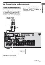
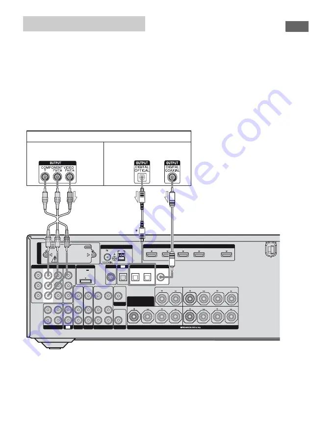
The following illustration shows how to
connect a DVD player.
It is not necessary to connect all the cords.
Connect audio and video cords according to
the jacks of your components.
Notes
• The COMPONENT VIDEO IN 2 jacks have been
assigned to the DVD player. If you connect your
DVD player to the COMPONENT VIDEO IN 1 or
IN 3 jacks, set “Input Assign” in the Input Option
menu (page 109).
• To input multi channel digital audio from the DVD
player, set the digital audio output setting on the
DVD player. Refer to the operating instructions
supplied with the DVD player.
• When connecting optical digital cords, insert the
plugs straight in until they click into place.
• Do not bend or tie optical digital cords.
Tip
All the digital audio jacks are compatible with
32 kHz, 44.1 kHz, 48 kHz, and 96 kHz sampling
frequencies.
* When you connect a component equipped with an
OPTICAL jack, set “Input Assign” in the Input
Option menu.
Connecting a DVD player
L
R
VIDEO
OUT
MONITOR
L
R
DC5V
0.7A MAX
HDMI
ANTENNA
DMPORT
IN 4
ASSIGNABLE (INPUT ONLY)
IN 2
IN 3
IN 1
OUT
AM
OUT
IN
SA-CD/CD/CD-R
VIDEO 1
IN
TV
AUDIO
IN
VIDEO
IN
SAT
AUDIO
OUT
AUDIO
OUT
VIDEO
OUT
OPTICAL IN
AUDIO
IN
VIDEO
IN
SUBWOOFER
AUDIO
IN
VIDEO
IN
BD
L
R
L
R
SPEAKERS
CENTER
FRONT A
SURROUND BACK/
FRONT B/
BI-AMP
TV
SIRIUS
L
R
SURROUND
SAT IN
BD IN
DVD IN
OPTICAL
COAXIAL
(for AUDIO)
EZW
-T100
IN 3
Y
P
B
/
C
B
P
R
/
C
R
OUT
ASSIGNABLE (INPUT ONLY)
COMPONENT VIDEO
IN 2
IN 1
MONITOR
DIGITAL
(ASSIGNABLE)
DVD player
A
B
A
Component video cord (not supplied)
B
Optical digital cord (not supplied)
C
Coaxial digital cord (not supplied)
C
Video signals
Audio signals


