5
Hooking Up the Components
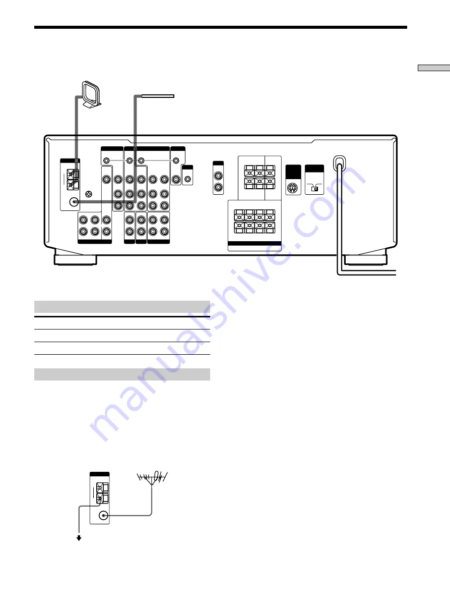
Antenna Hookups
SELECTOR
FRONT
IMPEDANCE
WIRELESS
REAR
SPEAKER
SPEAKERS
4
Ω
8
Ω
IMPEDANCE USE 8–16
Ω
REAR CENTER FRONT A + B
IMPEDANCE USE 4–16
Ω
F R O N T A O R B
+
R –
A
A
B
B
– L
+
+
R –
– L
+
REAR
FRONT
+
+
–
–
CENTER
R
L
R
L
MONITOR
WOOFER
AUDIO
OUT
VIDEO
OUT
CTRL S
IN
VIDEO
IN
VIDEO
OUT
VIDEO
IN
CTRL S
OUT
VIDEO
OUT
CTRL S
OUT
VIDEO
IN
VIDEO
IN
IN
L
R
L
R
RECOUT
IN
CENTER
WOOFER
CTRL S
STATUS IN
SIGNAL
GND
COAXIAL
FM
75
Ω
AM
AUDIO
IN
L
R
AUDIO
OUT
AUDIO
IN
AUDIO
OUT
AUDIO
IN
CTRL A1
y
y
5.1/DVD INPUT
ANTENNA
PHONO
TAPE/MD
MONITOR
VIDEO 1
VIDEO 2
TV / DBS
S-LINK
S-LINK
FRONT
REAR
IN
CD
Terminals for connecting the antennas
Connect the
To the
AM loop antenna
AM terminals
FM wire antenna
FM 75
Ω
COAXIAL terminal
Notes on antenna hookups
• To prevent noise pickup, keep the AM loop antenna
away from the receiver and TV.
• After connecting the FM wire antenna, keep it as
horizontal as possible.
z
If you have poor FM reception
Use a 75-ohm coaxial cable (not supplied) to connect the receiver
to an outdoor FM antenna as shown below.
Receiver
FM outdoor antenna
COAXIAL
FM
75
Ω
AM
y
ANTENNA
To ground
I m p o r t a n t
If you connect the receiver to an outdoor antenna, ground
it against lightning as shown in the illustration in the left
column. To prevent a gas explosion, do not connect the
ground wire to a gas pipe.
Note
Do not use the SIGNAL GND
y
terminal for grounding the
receiver.
Ground wire
(not supplied)
FM wire antenna
(supplied)
AM loop antenna
(supplied)
Содержание STR-DE525
Страница 19: ...19 Hooking Up and Setting Up the Speaker System ...
Страница 44: ...Sony Corporation Printed in Malaysia ...


