SRS-ZR7
15
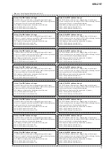
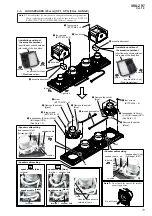
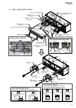
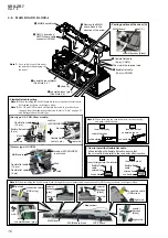
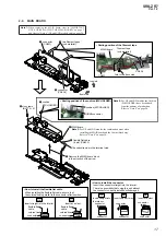
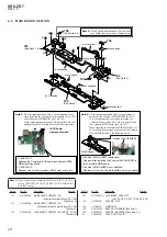
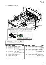
2-7. MAIN BOARD BLOCK-1
• Continued on 2-8 (page 16).
front side
bottom side
1
sheet (A)
1
sheet
(BOTTOM
FFC)
sheet (BOTTOM FFC)
4
four sheets (A)
sheet (A)
sheet (A)
2
flexible flat cable
(4 pin) (CN208)
3
flexible flat cable
(24 pin) (CN207)
5
screw
(BTTP
M2.6
u
8)
5
screw
(BTTP
M2.6
u
8)
5
screw
(BTTP
M2.6
u
8)
5
two screws
(BTTP
M2.6
u
8)
3DVWLQJSRVLWLRQRIWKHVKHHW$
3DVWLQJSRVLWLRQRIWKH
VKHHW$
3DVWLQJSRVLWLRQRIWKH
VKHHW%27720))&
The opposite side is
the terminal side.
connection cable
(GND strap)
connection cable (GND strap)
rib
screw hole
5
three screws
(BTTP
M2.6
u
8)
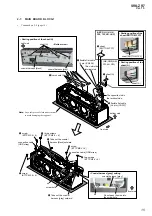
6
Take out the coaxial
harness [gray] outward.
coaxial harness [gray]
6
Take out the coaxial
harness [black] outward.
coaxial harness [black]
This side is the
terminal side.
–
%RWWRPYLHZ
–
right side
&RD[LDOKDUQHVV>JUD\@VHWWLQJ
rib
Do not pass the wire into
the screw hole.
coaxial harness [gray]
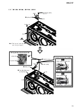
Note:
Lay a soft piece of cloth under the unit
to avoid damaging the top panel.
front side
$(3588.+.
637:.5$86
86&1'$5
7+/$&+
Ver. 1.3
Содержание SRS-ZR7
Страница 6: ...SRS ZR7 6 MEMO ...
Страница 8: ...SRS ZR7 8 MEMO ...


