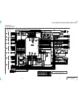
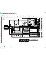
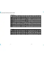

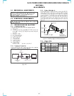


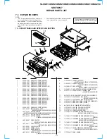
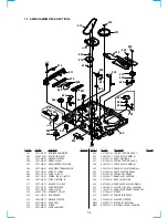
5-4
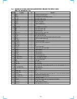
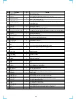
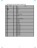
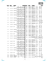
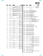
Pin No.
51
52
53
54
55
56
57
58
59
60
61
62
63
64
65
66
67
68
69
70
71
72
73
74
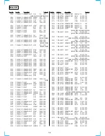
75
76
77
78
79
80
81
82
83
84
85
86
87
88
89
90
91
92
93
94
95
96
97
98
99
100
Pin Name
OSD W LEVEL
OSD V OUT
OSD Vcc
HLF (SLICER LPF)
OSD SECAM C IN
C V IN (C SYNC IN)
NUA
DEC/VTR
PDC DAV
AV CONT IN/C+DET
DIV CLK OUT/JOG LED CONT
TA MUTE
A MUTE
MTR 12V CONT.
SW 5V CONT.
FLD CS
SECAM ON
TO FLD DATA
18V CONT
FLD CLOCK
SCL
(VI/HF/TU/NICAM ZWEI/MOD/VPS/DNR)
SDA
(VI/HF/TU/NICAM ZWEI/MOD/VPS/DNR)
TO AV LINK
–14V CONT
C+ 5V CONT
CAP ERROR
DRUM ERROR
P FAIL
S REEL
T REEL
DMS+
DMS–
TU SW1
TU SW2
FROM AV LINK
SECAM DET
CAP FG
AMP Vss
DRUM FG
DRUM PG
AMP VREF OUT
AMP VREF IN
RC CHECK
CTL –IN
CTL +IN
AMP C
CTL AMP OUT
AMP Vcc
AVcc
24V CONT
I/O
I
O
I/O
I
I
O
I
I
O
O
O
O
O
O
O
O
O
O
I/O
I/O
O
O
O
O
O
I
I
I
I
I
O
O
I
I
I
I
I
I
I/O
I/O
O
O
Function
OSD white level input
OSD video signal output
Power supply input terminal for OSD/slicer (4.75 V to 5.25 V)
LPF connection terminal for slicer/AFC (This terminal is used as the HLF terminal
when C. Video is input to pin-56.)
Color signal input for SECAM OSD
Video signal input for tuner’s station selection, OSD and servo sync signal detection
(after passing filter)
Connected to Ground
Decoder/VTR switching
PDC/VPS signal reception identification input
CANAL+ connection identification input
Terminal of using JOGLED output or adjustment mode output of clock dividing frequency
Tuner audio mute signal output
Audio mute signal output
Motor 12 V power control signal
SW 5 V power control signal
Chip selection signal for display tube driver
SECAM ON signal/surround audio control (switched by destination)
Serial data out CH0 (FLD)
N.C.
Serial clock CH0 (FLD)
I2C clock (video/HiFi/tuner/ARC/modulator/VPS control)
I2C data (video/HiFi/tuner/ARC/modulator/VPS control)
SMART LINK data output for communication
Power save control
Power save control
Capstan error output
Drum error output
Power failure detection input
Supply reel sensor input
Take up reel sensor input
N.C.
N.C.
Turner system BG/L selection signal
Turner system BGL/L selection signal
SMART LINK data input for communication
SECAM identification input
Capstan FG input
Ground terminal for analog amplifier (connected to Vss)
Drum FG input
Drum PG input
Analog amplifier reference power supply output terminal
Analog amplifier reference power supply output terminal
No use (Fix to “L” on the outside for the terminal only for the input)
CTL signal input/output terminal
CTL signal input/output terminal
CTL amplifier AC Ground terminal
CTL amplifier output
Power supply input terminal for analog amplifier (connected to Vcc)
Power supply input and reference voltage input to A-D converter
N.C.
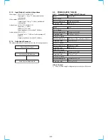
Содержание SLV-SE100
Страница 6: ...1 2 ...
Страница 7: ...1 3 ...
Страница 8: ...1 4 ...
Страница 9: ...1 5 ...
Страница 10: ...1 6 ...
Страница 11: ...1 7 ...
Страница 12: ...1 8 ...
Страница 13: ...1 9 ...
Страница 14: ...1 10 ...
Страница 15: ...1 11 ...
Страница 16: ...1 12 ...
Страница 17: ...1 13 ...
Страница 18: ...1 14 ...
Страница 19: ...1 15 ...
Страница 20: ...1 16 ...
Страница 21: ...1 17 ...
Страница 22: ...1 18E MEMO ...
Страница 28: ...2 6E MEMO ...
Страница 34: ...3 12E MEMO ...
Страница 58: ...5 6E MEMO ...
Страница 62: ...MEMO 6 6E ...
Страница 80: ...7 18E MEMO ...