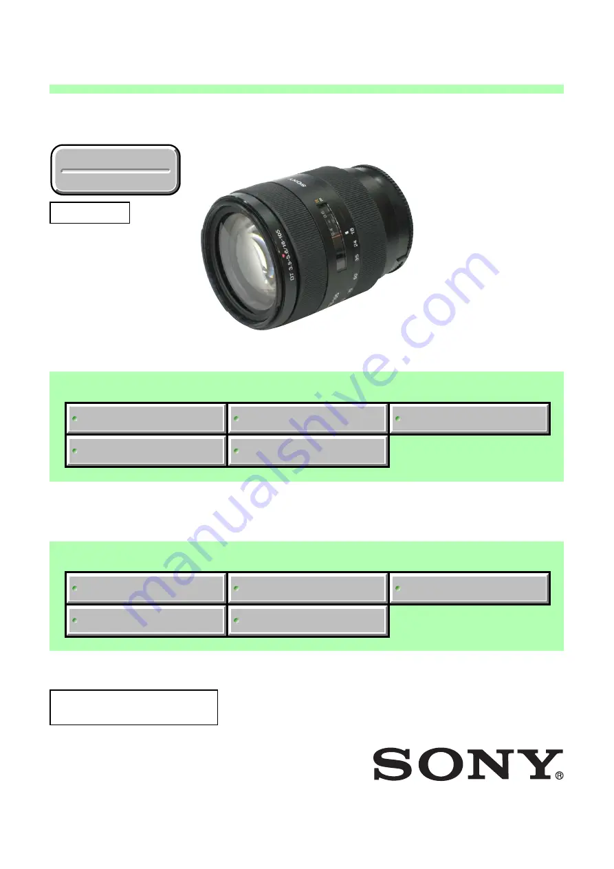
Sony SAL16105 - Zoom Lens - 16 mm Скачать руководство пользователя страница 1

SERVICE NOTE

SPECIFICATIONS

REPAIR PARTS LIST

DISASSEMBLY

ADJUSTMENTS

SERVICE MANUAL

Revision History

Revision History

Sony EMCS Co.

SAL16105 (DT 3.5-5.6/16-105) (DT 16-105mm F3.5-5.6)

SERVICE NOTE

SPECIFICATIONS

REPAIR PARTS LIST

DISASSEMBLY

ADJUSTMENTS

Link (Japanese)

Link (Japanese)

・レンズ投影器と完成検査治具について

分解図につきましては,英語版を
ご参照ください。

Link (English)

Link (English)

Ver. 1.3  2008.05

LENS FOR DSLR CAMERA

2008E0800-1

  © 2008.05

Published by Kohda TEC

9-852-220-14

US Model

Canadian Model

AEP Model

Chinese Model

Japanese Model

SAL16105

(DT 3.5-5.6/16-105) (DT 16-105mm F3.5-5.6)

• About the Lens Test Projector and Finished Inspection JIG

Revised-3

Replace the previously issued
SERVICE MANUAL 9-852-220-13
with this Manual.

Содержание SAL16105 - Zoom Lens - 16 mm

Страница 1: ...ENTS Link Japanese Link Japanese レンズ投影器と完成検査治具について 分解図につきましては 英語版を ご参照ください Link English Link English Ver 1 3 2008 05 LENS FOR DSLR CAMERA 2008E0800 1 2008 05 Published by Kohda TEC 9 852 220 14 US Model Canadian Model AEP Model Chinese Model Japanese Model SAL16105 DT 3 5 5 6 16 105 DT 16 105mm F3 5 5 6 About the Lens Test Projector and Finished Inspection JIG Revised 3 Replace the previously issu...

Страница 2: ...ormat focal length and angle of view are based on Digital Single Lens Reflex Cameras equipped with an APS C sized image sensor Minimum focus 2 m feet 0 4 1 3 2 Minimum focus is the shortest distance from the image sensor to the subject Maximum magnification X 0 23 Minimum f stop f 22 36 Filter diameter mm 62 Dimensions maximum diameter height mm in Approx 72 83 2 7 8 3 3 8 Mass g oz Approx 470 16 ...

Страница 3: ... clean heavy dirt don t use paint thinner ketone nor alcohol Insert the specific screws vertically to the part when installing a exterior part Be careful not to tighten screws too much 1 3 Unleaded Solder This unit uses unleaded solder Boards requiring use of unleaded solder are printed with the lead free mark LF indicating the solder contains no lead Caution Some printed circuit boards may not co...

Страница 4: ...6 Flexible Circuit Board Repairing Keep the temperature of the soldering iron around 270 C during repairing Do not touch the soldering iron on the same conductor of the circuit board within 3 times Be careful not to apply force on the conductor when soldering or unsoldering SAFETY RELATED COMPONENT WARNING COMPONENTS IDENTIFIED BY MARK 0 OR DOTTED LINEWITH MARK 0 ON THE SCHEMATIC DIAGRAMS AND IN T...

Страница 5: ...Adhesive bond B 10 J 6082 612 A Grease G 115 J 6082 627 A Grease G 116 J 6082 628 A Adhesive bond LOCTITE 460 or the equivalent NOTE FOR REPAIR Make sure that the flat cable and flexible board are not cracked of bent at the terminal Do not insert the cable insufficiently nor crookedly When remove a connector dont pull at wire of connector It is possible that a wire is snapped When installing a con...

Страница 6: ...Connection Board Rear Light Shield Barrel Back Adjustment Washer Zoom Barrel Zoom Rubber Ring Focus Rubber Ring Rear Barrel Cinuber Ring Focus Brush Zoom Brush Ground Brush 1 2 3 4 8 6 qs A A q qa 9 7 5 First Lens Holder Block G1 G2 1st Lens Stopper Barrel 2nd Lens Barrel Assy 2nd Block Adjustment Waser 3rd Lens Barrel Assy 4th Lens Block 4th Lens Barrel Hold Washer 3 4 Interval Adjustment Washer ...

Страница 7: ...k 10mm 10mm 10mm 1st Cam Ring Decoration Plate 2nd Decoration Plate 2nd Block Adjustment Washer 2nd Lens Barrel Assy Chip A for universal wrench J 6082 609 1 See Page 2 4 2 3 Note Assembling Align the Notch with the Mark A G1 G2 First Lens Holder Block Mark A Notch Note Assembling Align the Mark B with the Mark A Mark A Mark B B 10 B 10 Note Assembling Make the lens upside down 4 EXPLODED VIEW 2 2...

Страница 8: ...ns Block 3 4 Interval Adjustment Washer 3rd Lens Barrel Assy Tweezers Note Assembling Align the Large Cutout with the Notch Large Cutout Notch Notch Universal wrench J 6082 609 A Chip A for universal wrench J 6082 609 1 8 3rd Lens Barrel Assy 2 2 2 See Page 2 5 From Page 2 3 PARTIAL BLUR ADJUSTMENT Lens made upside down ...

Страница 9: ... No Convex in inner circle of the Zoom Rubber Ring Rear Light Sheild Barrel Connection Board Ground Spring Lens Mount Block A See Page 2 8 See Page 2 6 HELP02 01 Back Adjustment Washer Coupler Adjustment Washer AF Coupler Ground Brush 6 5 Zoom Rubber Ring Convex No Convex Portion 2 2 1 From Page 2 4 B 40 B 40 FLANGE BACK ADJUSTMENT FLANGE BACK ADJUSTMENT G 118 ...

Страница 10: ... Zoom Barrel Note Assembling Zoom Brush Zoom Brush Polyester Tape Black 10mm 7X13mm Polyester Tape Black 10mm 7X13mm Note Assembling Notches Zoom Coupling Pins Note Assembling Align the Notches with the Zoom Coupling Pins B C From Page 2 5 HELP02 02 ZOOM BRUSH POSITION ADJUSTMENT Taping Position Taping Position G 118 G 118 Cinuber Ring Rear Barrel Assy See Page 2 7 See Page 2 8 ...

Страница 11: ...2 6 HELP02 03 Inner Barrel Assy Focus Differential Ring HELP02 03 HELP02 04 Focus Differential Ring Focus Rubber Ring Inner Barrel Assy 2 2 3 See Page 2 9 2 2 4 See Page 2 14 Be careful about the Focus Cam Barrel isn t off the position because of it is easy to come off q Focus Brush Set the focus to near position Focus Brush Screw Projection B 10 FOCUS BRUSH POSITION ADJUSTMENT Make the lens upsid...

Страница 12: ...dex Chip Mount Index Rear Barrel Assy Note Assembling Align the Cutout with the Hole for the Coupler Note Assembling Align the Lever of the Preset Ring with the Space A Install its surface the edge is planed up Note Assembling Note Assembling Note Assembling Large Ring of the Main Spring Small Ring of the Main Spring Hook of the Preset Ring O 20 G 115 LOCTITE 460 or the equivalent All the grease O...

Страница 13: ...e operate plate lever 4 Pass Connection board through the lens mount block and in the middle of preset lever insertion turn the lens mount block in the arrow direction adjust screw hole positions and secure with four screws Apply the grease G 118 Apply the grease G 118 Apply the grease G 118 to 3 5 mm from the edge on rear side of claw Claw Lens Mount Block Apply the anti diffusion agent A 20 Back...

Страница 14: ...e zoom barrel as shown in the figure 2 Apply the grease G 115 to the zoom barrel as shown in the figure 3 Apply the grease G 118 to the zoom barrel as shown in the figure Apply the anti diffusion agent A 20 All circumferences Zoom Barrel Apply the grease G 115 All circumferences Apply the grease G 115 All circumferences Zoom Barrel Zoom Barrel Apply the grease G 118 All circumferences Zoom Barrel ...

Страница 15: ...ture operate plate lever is not to touch the fixed barrel assy 4 Confirm the focus differential ring moves synchronously with the focus operation ring moving by turning the focus operation ring to the both directions near infinity Projection Projection Focus Differential Ring Fixed Barrel Assy Focus Rubber Ring Fixed Barrel Assy Lever of the Focus Ring Lever of the Focus Ring Inner Barrel Assy Foc...

Страница 16: ... differential ring as shown in the figure 2 Turn the aperture operate plate lever in the arrow direction 3 Install the focus differential ring while inserting the lever of the focus cam barrel into the groove on the focus differential ring Apply the grease G 118 Apply the grease G 116 Focus Differential Ring Groove Lever of the Focus Cam Barrel Aperture Operate Plate Lever ...

Страница 17: ...ing assembled with rear barrel assy with the adhesive bond B 10 be sure to apply the adhesive bond B 110 to the following 6 portions Cinuber Ring Rear Barrel Assy Rear Barrel Assy 20mm 20mm 20mm B 110 Apply covering the point rear barrel assy is in contact with cinuber ring Cinuber Ring Cinuber Ring Rear Barrel Assy Rear Barrel Assy Apply the adhesive bond B 110 Apply the adhesive bond B 110 Apply...

Страница 18: ...lock 2 Guide Roller 3rd Lens Block 1 Guide Roller 3rd Lens Block 1 Guide Roller 3rd Lens Block 1 Guide Roller Focus Cam Barrel HELP03 01 HELP03 02 HELP03 02 HELP03 02 2 3 4 Moving Frame Assy See Page 2 10 B 40 B 40 B 40 2 2 2 From Page 2 7 Make the lens upside down Lens made upside down 2 2 3 INNER BARREL ASSY EXPLODED VIEW ...

Страница 19: ...l Zoom Cam Ring Two Scerw Holes of the Fixed Barrel Mark 1st Lens Block Guide Barrel Front Lens Barrel R Assy Note Assembling Align the Two Scerw Holes of the Fixed Barrel with the Mark as shown in the figure Note Assembling Set the position the screw hole on 1st Lens Block Guide Shaft can be seen through the screw hole on the Front Lens Barrel Adjust the phase between Zoom Cam Ring and Fixed Barr...

Страница 20: ...age 2 10 Front Lens Barrel Assy Projections 1st Lens Block Guide Barrel 1st Lens Block Guide Barrel Grooves Note Assembling G 116 G 116 B 40 B 40 A From Page 2 10 1st Lens Block Operation Roller 7 HELP03 03 HELP03 03 See Page 2 12 First Cam Ring Engage three projections with three grooves ...

Страница 21: ...40 B 40 B 40 2nd Lens Block Guide Roller 2nd Lens Block Hold Shaft 2nd Lens Block Guide Shaft 2nd Guide Roller Spring 400 H2 Second Lens Holder Second Lens Holder See Page 2 13 G 116 G 116 Second Lens Holder Focus Guide Pin From Page 2 11 HELP03 04 HELP03 04 ...

Страница 22: ...m Cross section Cross section Inside Outside 10mm Zoom Cam Barrel Holder Universal wrench J 6082 609 A Chip A for universal wrench J 6082 609 1 Inner screw portion G 116 Zoom Torque Spring Washer Zoom Torque Spring Zoom Cam Ring Cam Ring Support Sheet Fixed Barrel G 116 G 116 G 116 G 116 G 116 G 116 ...

Страница 23: ...rtion of 3 4 moving frame assy position without 4th cam guide and aperture operation lever 3 Turn the focus cam barrel in the arrow direction to engage the focus guide pin with the groove on the focus cam barrel Focus Cam Barrel Inner Barrel Assy Apply the grease G 116 Apply the grease G 116 Mark 4th cam guide Guide of the 3 4 Moving Frame Assy Lever Aperture Operate Plate Lever Focus Cam Barrel F...

Страница 24: ...igure 4 Shorten the whole block and install three 3rd lens block 2 guide rollers 5 Apply the adhesive bond B 40 to about two threads from the tips of stopper screws and tighten them 3 4 Moving Frame Assy 3 4 Moving Frame Assy Fixed Barrel Install with setting the projection A away from the projection B Zoom Cam Ring Projection A Groove A Projection B Projection A Groove A Fig a 3 4 Moving Frame As...

Страница 25: ...nstall them 4 Install the three 1st lens block operation rollers 5 Apply the adhesive bond B 40 to about two threads from the tips of stopper screws and tighten them First Cam Ring First Cam Ring Two Screw Holes Two Screw Holes Fixed Barrel Two Screw Holes Stopper of the Zoom Cam Ring Stoppers of the Zoom Cam Ring Stopper of the Zoom Cam Ring Fixed Barrel Assy Fixed Barrel Assy Screw Hole A Screw ...

Страница 26: ...ock guide shaft and 2nd guide roller spring 400 H2 4 Apply the adhesive bond B 40 to about two threads from the tips of stopper screws and tighten them Cutout Cutout Two Screw Holes Two Screw Holes Groove Groove Stoppers of the Zoom Cam Ring Second Lens Holder Second Lens Holder Fixed Barrel Fig a Fig b Fixed Barrel Fixed Barrel Assy Zoom Cam Ring Zoom Cam Ring Scratched Line Scratched Line 2nd Le...

Страница 27: ...ut together the zoom cam ring and the fixed barrel while adjusting the cutout portion to two screw holes on the fixed barrel 5 Confirm the projection of the zoom cam ring engages with the groove of the fixed barrel by turning the zoom cam ring Zoom Cam Ring Cam Ring Support Sheet Apply the grease G 116 Apply the grease G 116 Zoom Cam Ring Cutout Portion Projection Fixed Barrel Groove Zoom Cam Ring...

Страница 28: ...g Part A Part A Pinch Clutch Block Cut Portion Projection Focus Ring Reinforcement Plate G 116 B 110 B 110 B 110 B 10 B 110 10mm 10mm See Page 2 15 On disassembling remove by turning Part A 2 2 2 From Page 2 7 Universal wrench J 6082 609 A Chip B for universal wrench J 6082 609 2 PINCH CLUTCH TORQUE ADJUSTMENT Make the lens upside down 2 2 4 FIXED BARREL ASSY EXPLODED VIEW ...

Страница 29: ...E PLATE POSITION ADJUSTMENT 7 Focus Stopper Gear Base Plate CL 002 Block Gear Shaft Fixed Barrel R Assy Gear A Focus Ring Focus Scale Plate Focus Scale Plate HELP04 05 HELP04 07 HELP04 06 Focus Ring Polyester Tape Black 10mm 7X25mm 8 9 6 4 From Page 2 14 G 118 G 118 G 116 5 Make the lens upside down ...

Страница 30: ...2 617 A 1 Install the support plate and put it in the arrow direction 2 Apply the adhesive bond B 110 between the support plate and the outer cover block carefully as shown below Apply the grease G 118 Lib of the Outer Barrel Center Mount Shielding O Ring Mount Shielding O Ring Allow mount shielding O ring to absorb all the grease G 116 it can To a little over the top Apply the adhesive bond B 110...

Страница 31: ...ockwise until it stops and install it HELP04 04 1 Be sure to put the focus ring reinforcement plate so that its adhesive surfaces don t go out to the pinch lever hold pin Apply the adhesive bond B 110 Apply the adhesive bond B 110 Apply the adhesive bond B 110 Cutout Cutout Projection Projection Projection Fixed Barrel R Assy Projection Outer Cover Block Outer Cover Block Outer Cover Block Focus R...

Страница 32: ...he long holes of the outer barrel and tighten two screws temporarily 3 Turn the focus ring in the near position in the arrow direction Note Be sure to position the focus scale plate as shown in the picture 4 While pushing focus stopper to left side tighten two screws temporarily Note Tighten lightly to the end and loosen 1 4 turn Note Refer to Focus shift Adjustment for tightening up Focus Stopper...

Страница 33: ...ring and fix it with the polyester tape Black 10mm 7 25mm Note Confirm the part A slides in the arrow direction Note Put the focus scale plate so that it is not out of the groove on the focus ring Apply the grease G 116 Focus Scale Plate Focus Scale Plate Focus Scale Plate Focus Ring Groove of the Focus Ring Part A Hole B Polyester Tape Black 10mm 7X25mm Polyester Tape Black 10mm 7X25mm A A Hole B...

Страница 34: ...o be fitted to the corners C and D Fig g h 7 Peel off the release paper on the part E of CL 002 block stick it to be fitted to the shape of outer barrel Fig i j Note Be to stick it so that there is no floating point at the part F Fig j 8 Stick it fitting to the edge of outer barrel Fig k Note Be sure not to bring it out to the arrow direction 9 Wrinkle the flexible board while pulling slightly CL ...

Страница 35: ...1 G2 3 A 1334 689 A FIRST LENS HOLDER BLOCK 4 3 270 620 02 1ST CAM RING DECORATION PLATE 5 3 210 198 02 2ND DECORATION PLATE 6 3 218 903 01 SCREW TAPPING P1 M1 7X3 5 7 A 1279 372 A 2ND LENS BARREL ASSY 8 A 1319 824 A 3RD LENS BARREL ASSY 9 Selection parts 3 4 INTERVAL ADJUSTMENT WASHER Note 1 10 A 1279 371 A 4TH LENS BLOCK 11 3 210 177 01 4TH LENS BARREL HOLD WASHER 12 3 292 495 01 2ND BLOCK ADJUS...

Страница 36: ...ENT WASHER A to E Note 1 70 2 684 234 01 PRESET RING HOLDING PLATE 71 2 688 406 01 MAIN SPRING 72 Selection parts PRESET RING Note 1 73 A 1279 383 A MAIN SPRING GUIDE BLOCK 74 2 684 244 01 STOPPER SCREW M1 4X1 2 75 3 210 040 01 REAR LIGHT SHEILD BARREL 76 7 627 551 98 PRECISION SCREW P 1 4X2 2 77 2 684 065 01 GROUND SPRING 78 2 684 066 01 TAPPING SCREW M1 7X4 0 Ref No Part No Description ns not su...

Страница 37: ...arts 3RD LENS BLOCK 2 GUIDE ROLLER Note 1 110 A 1279 367 A 3 4 MOVING FRAME ASSY 111 3 210 049 01 SECOND LENS HOLDER 112 Selection parts FOCUS GUIDE PIN Note 1 113 3 210 052 01 2ND LENS BLOCK HOLD SHAFT 114 3 210 047 01 FIXED BARREL 115 3 210 046 01 ZOOM CAM RING 116 Selection parts 3RD LENS BLOCK 1 GUIDE ROLLER Note 1 117 Selection parts 2ND LENS BLOCK GUIDE ROLLER Note 1 118 3 282 710 01 2ND GUI...

Страница 38: ...ACK 10mm Note 1 155 3 210 199 01 FOCUS RING 156 3 210 227 01 FOCUS STOPPER 157 2 685 720 01 PHI 4 HEAD SCREW M1 6X2 1 158 A 1436 966 A FIXED BARREL R ASSY 159 3 281 724 02 SUPPORT PLATE 160 A 1319 823 A OUTER COVER BLOCK 161 3 270 824 01 GEAR SHAFT 162 3 212 711 01 GEAR A 163 3 210 212 01 GEAR BASE PLATE 164 3 271 885 01 SCREW TAPPING P2 M1 7X3 5 165 2 899 301 01 MOUNT SHIELDING O RING 166 A 1359 ...

Страница 39: ...Part No Description 3 210 265 01 PRESET RING 3 275 411 01 PRESET RING L 3 275 412 01 PRESET RING S Ref No 107 Select the type of part according to the operation load of the associated parts Part No Description 3 210 078 02 1ST LENS BLOCK GUIDE ROLLER D 4 30 3 210 078 12 1ST LENS BLOCK GUIDE ROLLER D 4 31 3 210 078 22 1ST LENS BLOCK GUIDE ROLLER D 4 32 Ref No 109 Select the type of part according t...

Страница 40: ...LOCK GUIDE ROLLER D 6 51 3 210 051 12 2ND LENS BLOCK GUIDE ROLLER D 6 52 3 210 051 22 2ND LENS BLOCK GUIDE ROLLER D 6 53 Ref No 126 Select the type of part according to the operation load of the associated parts Part No Description 3 210 082 01 1ST LENS BLOCK OPERATION ROLLER D 4 33 3 210 082 11 1ST LENS BLOCK OPERATION ROLLER D 4 32 3 210 082 21 1ST LENS BLOCK OPERATION ROLLER D 4 31 ...

Страница 41: ...s Other accessories 3 219 252 01 MANUAL INSTRUCTION JAPANESE ENGLISH FRENCH SPANISH SIMPLIFIED CHINESE 3 219 252 11 MANUAL INSTRUCTION GERMAN DUTCH SWEDISH ITALIAN AEP 3 219 252 21 MANUAL INSTRUCTION PORTUGUESE RUSSIAN TRADITIONAL CHINESE KOREAN ARABIC AEP Lens Hood SH105 3 210 270 01 Front Lens Cap X 2179 384 1 Rear Lens Cap 2 683 615 01 ...

Страница 42: ...を確認してください 他の付属品 3 219 252 01 取扱説明書 日本語 英語 フランス語 中国語 簡字体 スペイン語 下記に参考として 海外向取扱説明書の 部品番号と言語について記載しています 3 219 252 11 DT 16 105mm F3 5 5 6 ドイツ語 オランダ語 イタリア語 スウェーデン語 3 219 252 21 DT 16 105mm F3 5 5 6 ポルトガル語 アラビア語 中国語 繁字体 ロシア語 韓国語 レンズフード SH105 3 210 270 01 前レンズキャップ X 2179 384 1 後レンズキャップ 2 683 615 01 ...

Страница 43: ...ulator 2 Note Color Calculator 2 is downloadable from the ESI homepage Fig 4 1 1 Personal computer Note 1 AE master lens J 6082 597 A Flange back gauge 43 50mm J 6082 608 A Maximum Aperture jig J 6082 640 A Aberration measuring cap 62mm SAL16105 J 6082 679 A Flange back tester J 6082 606 A A mount attachment J 6082 607 A Lens test projector J 6082 605 A Note 3 1000 mm Collimator 110V J 6082 604 A ...

Страница 44: ...a 15 M Byte or more recommended USB terminal Standard equipment Graphics 32 000 colors or more recommended VGA monitor Note 2 Attach the chart to the 1000 mm collimator as shown in Fig 4 1 2 Fig 4 1 2 Note 3 Connect the variable transformer Output voltage AC 100 V to the lens test projector Note 4 Finished Inspection JIG is AC 100 V only Align the marks 1000 mm collimator Chart ...

Страница 45: ...tment Flange Back f F Check Section 4 6 Flange Back f F Adjustment Adjustment Parts Back Adjustment Washer Coupler Adjustment Washer Preset Ring 2nd Block Adjustment Washer Focus Shift Amount of spherical aberration Section 4 7 Finished Inspection Actuator Checker 2 Section 4 12 Drive System Zoom Brush Position Check Adjustment Section 4 11 Pinch Clutch Torque Adjustment Section 4 9 Focus Scale Pl...

Страница 46: ...e 1 Lap top PC with PC card slot on which Windows XP runs Note 2 Obtain the PC card setup file InstaCal zip from the ESI homepage Note 3 Obtain the lens adjustment program ActuatorChecker2 Ver x x x x zip from the ESI homepage 1 Download of PC card setup file InstaCal zip 1 Create the MCC folder in the C drive Fig 4 1 3 2 Download the file from Service Fixture and Software of ESI homepage and save...

Страница 47: ...ract destination folder Fig 4 1 5 6 The window returns to the menu to specify the extract destination folder Click Unzip Fig 4 1 6 7 When the window below appears click OK Fig 4 1 7 8 Return to the menu to specify the extract destination folder Then click Close to close the window ...

Страница 48: ...Setup of PC Card 1 Double click InstaCal msi in C MCC folder to begin the installation Fig 4 1 8 2 The menu to begin the installation appears Click Next Fig 4 1 9 3 Specify the install destination folder As the default is used for it click Next Fig 4 1 10 ...

Страница 49: ...he installation is completed Click Finish Note To refer to the readme file check the Show the readme file and click Finish Fig 4 1 12 6 To make the configuration installed effective the window to prompt the restart appears Click Yes to restart the PC Note If a device is connected without restarting the program may not work properly Fig 4 1 13 ...

Страница 50: ...C insert the PC CARD DIO48 in the PC card slot 8 The software installation window appears Click Install the software automatically Recommended Fig 4 1 14 9 The software is detected and installed When the window below appears click Finish to terminate the installation Fig 4 1 15 ...

Страница 51: ...n the Windows setting the window below may differ Fig 4 1 16 2 When PC CARD DIO48 is detected the window below appears Confirm that the PC CARD DIO48 is checked Note Depending on the slot inserted the slot No differs Fig 4 1 17 3 Confirm that PC CARD DIO48 is recognized as Board 0 Note If not recognized as Board 0 the program does not work properly Fig 4 1 18 4 Click File Exit to terminate InstaCa...

Страница 52: ...e 1 Download the file ActuatorChecker2 VerX X X X zip from Service Fixture and Software of ESI homepage save and extract it 2 Start up ActuatorChecker2 exe from an arbitrary folder 3 If PC CARD DIO48 is properly installed the window below appears Note The version of ActuatorChecker2 might be updated Fig 4 1 19 ...

Страница 53: ...ure is executed Equipment Personal Computer Finished Inspection JIG AC100 V only Lens Adjustment Program ActuatorChecker2 exe 1 Connect equipment and checking lens as shown Fig 4 1 20 Fig 4 1 20 2 Turn on the finished inspection JIG 3 Turn on the personal computer 4 Start up ActuatorChecker2 exe from an arbitrary folder conform that start up program normally Note Turn off the finished inspection j...

Страница 54: ...ker2 exe 2 Depending on the initial startup or setting made at the previous startup the window differs When the Japanese window appears click the Set up button Change the language to English Note When any button is clicked the Serial window appears The window to enter the lens serial number appears Fig 4 1 21 Fig4 1 22 ...

Страница 55: ...that all of the items are set and click OK Fig 4 1 23 4 1 6 About Inspection Procedure of Lens Adjustment Program ActuatorChecker2 The inspection method has the method of executing the method of inspecting the corresponding model as everything continues and the inspection of each item one by one Click START from the start up window when you inspect the corresponding model as everything continues ...

Страница 56: ...ages under the following conditions and save them Note Shoot the center of the luminance surface three times with the master lens and checking lens Setting of Luminance box Luminance EV12 Setting of Lens Zoom Wide end focal length 16mm Focus Infinity end Setting of Camera ISO 100 Exposure Mode M shutter Speed 1 125 Aperture F5 6 Focus Mode MF Metering Center weighted Preset white balance Tungsten ...

Страница 57: ... lens 1 Start the Color Calculator 2 Fig 4 2 2 2 Read the image from the file menu Fig 4 2 3 3 Set the Color Calculator 2 as follows Measured value display Display menu RGB L a b Measuring method Display menu Center Single Area Fig 4 2 4 Color space Edit menu sRGB Fig 4 2 5 Area size for calculate Edit menu Option 256 256 Pixels Fig 4 2 6 ...

Страница 58: ...es shoot with checking lens b Fig 4 2 7 3 Checking Method 1 Calculate aperture error using the following formula and check that the aperture error is within the specification Aperture error Average G value of checking lens b Average G value of master lens a Specification Aperture error 25 to 0 Wide end 16mm 2 When the aperture error is out of specification perform 4 2 2 Aperture Diameter Adjustmen...

Страница 59: ...hesive bond B 10 Maximum Aperture Jig Universal Wrench Chip A for Universal Wrench Chip B for Universal Wrench 1 Preparation 1 Remove parts indicated in Fig 4 2 8 from the lens unit 2 Set the zoom to 16mm 3 Install the maximum aperture jig and open the aperture Fig 4 2 8 1st Lens Stopper Barrel 2nd Lens Barrel Assy G1 G2 First Lens Holder Block 1st Cam Ring Decoration Plate 2nd Decoration Plate 2n...

Страница 60: ...rance Repeat the confirmation and adjustment until the aperture tolerance meets the specification 4 After completing the adjustment apply the adhesive bond B 10 to the three indicated locations Fig 4 2 9 Fig 4 2 9 Aperture Unit Holding Spring Ø12 15mm Example of confirmation of the diameter of inscribing circle of the aperture Cut a paper in width of 12 15mm Confirm by attaching this paper to the ...

Страница 61: ...tachment and hold them together 4 Turn the focusing knob of the flange back tester so that fine scratches on the flange back gauge 43 50mm is the sharpest Note Turn the knob in the direction of the arrow of Fig 4 3 2 for correct reading Fig 4 3 2 5 Turn the scale ring of the dial gauge until the long pointer indicates 0 Note This position is the flange back f F 43 50 mm Memorize the position of sh...

Страница 62: ...ification of the Table 4 3 1 is satisfied CB Phenomenon that seems that color flared remains in one direction of ring chart at the best focus AS Phenomenon that seems that color of ring chart divides into direction of cross at the best focus Fig 4 3 5 Specification WIDE TELE CB 0 04mm or less 0 13mm or less AS 0 02mm or less 0 06mm or less Table 4 3 1 5 When the CB and AS of the checking lens is o...

Страница 63: ...ce Focal length f mm distance m 16 1 07 50 3 1 105 4 Table 4 4 1 1 Perform the following steps 1 to 3 and incorporate the internal lenses of the lens test projector according to the checking focal length 1 Open the lid of the lens test projector 2 Pull up and turn the fixed levers on the right and left sides of the lens test projector 3 Remove or insert the lens Note Be sure to have the right posi...

Страница 64: ...mp switch to ON Fig 4 4 2 4 Turn the focus ring of the checking lens until the chart image projected on the screen is the sharpest at the center y 0 5 Set the plane mirror to the center of the projected image y 0 and adjust the projector position so that the mirror reflects the light to the center of the lens Distance Lens test projector Chart Fan switch Lamp switch Plane mirror Screen A mount att...

Страница 65: ...s which appears on screen when focus is beyond maximum revolving power as shown in Fig 4 4 4 Do not confuse spurious resolution for the smallest pitched lines Fig 4 4 4 4 Change the focal length zoom and distance of the checking lens and check that the all readings y 0 saggital S and meridional M at y 9 or 12 at each focal length zoom and distance is within the specification of the Table 4 4 2 Spe...

Страница 66: ...if necessary 1 Set the focal length of lens to 105 mm and adjust the focus so that the center y 0 reaches the maximum resolution 2 Check projective resolving power at reach peripheral point of y 12 If the projective resolving power does not meet the specification perform the following 1 Rotate the 4th lens block adjust the defective parts to out of picture frame 2 If the adjustment is impossible a...

Страница 67: ...ocused point caused by the change of focal length are described Equipment 1000mm Collimator Flange back Tester A mount Attachment Flange back Gauge 43 50mm Adhesive bond B 10 1 Preparation 1 Remove parts indicated in Fig 4 5 1 from the lens unit 2 Execute 1 Preparation of 4 3 OPTICAL AXIS CHECK ADJUSTMENT Fig 4 5 1 Zoom Ring Reinforcement Plate Zoom Rubber Ring ...

Страница 68: ...that the flange back value on TELE end becomes 0 15mm against it on WIDE end At the same time the f 70 flange back value should be more than 0 03mm 7 While holding focus operation ring at TELE end move two focus stopper screws in the arrow direction and tighten them at the position the two screws stops lightly Note Be sure to hold a screw tightly not to move on tightening screw 8 Confirm the focus...

Страница 69: ...hod 1 Calculate the flange back f F of the checking lens using the following formula and check that the specification of the Table 4 6 1 is satisfied Flange back f F of the checking lens Flange back gauge Number of short pointer revolution Reading of long pointer Specification f mm f F mm 16 44 54 to 44 70 24 44 54 to 44 85 35 50 70 90 105 44 54 to 44 90 Table 4 6 1 2 When the flange back f F of t...

Страница 70: ...he thickness of back adjustment washer with a micrometer or a caliper Refer to Table 4 6 2 In case of negative value of shift amount X make the back adjustment washer thinner by x In case of positive value of shift amount X make the back adjustment washer thicker by x Back Adjustment Washer Part No Description thickness mm 2 688 527 01 BACK ADJUSTMENT WASHER A 0 05 3 218 900 01 BACK ADJUSTMENT WAS...

Страница 71: ...he shift amount X and replace the preset ring Part No Description Shift amount X mm Distinction 3 275 412 01 PRESET RING S 0 to 0 3 less than The groove in the top is shallow 3 210 265 01 PRESET RING 0 3 to 0 9 less than The groove in the top is none 3 275 411 01 PRESET RING L 0 9 or more The groove in the top is deep Table 4 6 4 Fig 4 6 2 Preset Ring L Preset Ring Preset Ring S ...

Страница 72: ... washer thicker In case of negative of flange back value make the 2nd block adjustment washer thinner 2ND BLOCK ADJUSTMENT WASHER Part No t mm 3 292 495 01 0 05 Note 2nd block adjustment washer that can be used for service is only thickness of 0 05 mm Except when you replace the 2nd lens barrel assy the thickness do not be changed from shipping Fig 4 6 3 2nd Lens Barrel Assy 2nd Block Adjustment W...

Страница 73: ... the lens aperture to the open aperture position and measure the flange back f F 2 Set the aberration measuring cap 62mm F8 equivalent on the tip of lens as shown in the Fig 4 7 1 then measure the flange back f F Fig 4 7 1 3 Calculate amount of focus shift using the following formula and check that the specification is satisfied Note The focus shift amount of the checking lens is difference betwee...

Страница 74: ...nity Mark Infinity Mark Pointer Adjustment by tweezers 2 Adjustment Procedure 1 Set the zoom to TELE end and the focus to infinity end 2 Adjust the pointer to the center of mark by moving both right and left focus scale plate with tweezers Note Be sure to hold tightly not to turn focus operation ring 3 Turn the focus ring from nearby infinity end to near end then return to infinity end and confirm...

Страница 75: ...ver hold pins 4 Rotate the focus ring so that the pinch lever fixing hole of torque ring A can be shifted When rotating clockwise the focus ring facing the lens up the torque becomes weak When rotating counterclockwise the focus ring facing the lens up the torque becomes strong 5 Apply the adhesive bond LOCTITE460 to the tip of pinch lever hold pin and tighten it Fig 4 9 1 Focus Rubber Ring Focus ...

Страница 76: ...nd B 10 1 Preparations 1 Take the mount side of lens apart to the rear barrel assy and install the lens mount and the rear light shield barrel Fig 4 10 1 2 Connected to equipment with checking lens Refer to Section 4 1 4 3 Start up of ActuatorChecker2 exe 4 Click Set up and perform the initial setting Refer to Section 4 1 5 Rear Light Sheild Barrel Lens Mount Block Cinuber Ring Rear Barrel Assy Zo...

Страница 77: ...ble unit with tweezers Then loosen two screws fixing the focus brush Fig 4 10 2 3 Click the Search Focus Adj Point Fig 4 10 3 4 In case of the focus is at the focus adjustment point near position or infinity position the pop up window as shown below appears on the screen and tighten up two screws secured the focus brush at the point Fig 4 10 4 Fig 4 10 5 Main Flexible Unit Set the focus near posit...

Страница 78: ...th setting it to near position or infinity position again 3 In case of error display in the Search Focus Adjustment Point 1 When the error display and the NG display appear to the pop up window press the ENTER key to return to the initial window and push ENTER key 2 Move the position of focus brush right and left and perform 2 Adjusting Method again Projection Focus Brush Screw Apply the adhesive ...

Страница 79: ...Adjustment Program Actuator checker2 exe 1 Preparations 1 Remove parts indicated in Fig 4 11 1 from the lens unit Fig 4 11 1 2 Connected to equipment with checking lens Refer to Section 4 1 4 3 Start up of ActuatorChecker2 exe 4 Click Set up and perform the initial setting Refer to Section 4 1 5 Polyester Tape Black 10mm 7X13mm Ground Brush Zoom Rubber Ring Zoom Brush ...

Страница 80: ...Adjusting Method 1 Set the zoom to TELE position 2 Peel off the polyester tape Fig 4 11 2 3 Click the Search Zoom Adj Point Fig 4 11 3 Polyester Tape Black 10mm 7X13mm Polyester Tape Black 10mm 7X13mm Zoom Brush Zoom Brush Flexible Pattern R Part Zoom Brush ...

Страница 81: ...oesn t go out of order with setting it to TELE position or WIDE position again 3 In case of error display in the Search Zoom Adjustment Point 1 In spite of the zoom is at the zoom adjustment point TELE position or WIDE position the pop up window as shown below appears on the screen find out the zoom adjustment point by adjusting from right to left the part R of the zoom brush is going to be at the...

Страница 82: ...up of ActuatorChecker2 exe 3 Click Set up and perform the initial setting Refer to Section 4 1 5 2 Checking Method 1 Click START Fig 4 12 1 2 The Serial window appears Input the lens serial number Note When OK is clicked without inputting the serial number the date executed is displayed on the completion window of each item Fig 4 12 2 3 The message Move Zoom to Wide position Then push ENTER is dis...

Страница 83: ...ER key Fig 4 12 5 6 When the wide position check finishes normally the message Reverse Zoom to Tele position at about 5sec is displayed on the pop up window Set the zoom to the tele position and press down the ENTER key Fig 4 12 6 7 When the tele position check finishes normally the message Move Focus to Near position Then push ENTER is displayed on the pop up window Set the focus to near position...

Страница 84: ...ge Reverse Focus to infinity position at about 5sec is displayed on the pop up window Set the focus to infinity position press down the ENTER key Fig 4 12 10 11 When the ROM Data Inspection finishes normally the message Select dSB Then push ENTER Being based on the focus shift amount calculated by 4 7 FOCUS SHIFT CHECK ADJUSTMENT APERTURE AMOUNTOF SPHERICAL ABERRATION select the button and perform...

Страница 85: ... 3 Earth Turn On Check 1 Remove the zoom rubber ring 2 Check the conduction between the lens mount block and the ground brush Note Be sure to check the conduction entirely the zooming by turning from WIDE end to TELE end Fig 4 12 14 3 If no conduction confirm whether the ground brush and the lens mount block are abnormal ...

Страница 86: ...lay and the NG display appear to the pop up window confirm the cause based on the content of the display The following pop up window is one example Fig 4 12 15 Zoom Adjustment Point Fig 4 12 16 Zoom Pattern Fig 4 12 17 Focus Adjustment Point Fig 4 12 18 Focus Pattern Fig 4 12 19 ROM Data Fig 4 12 20 ...

Страница 87: ...離 1 mm 24 157 5 レンズ群一枚 11 15 画角 1 83 15 1 ここでの 35mm判換算焦点距離および画角とは APS Cサイズ相当の撮像素子を搭載したデジタル一眼レフカメラでの値を表します 最短撮影距離 2 m 0 4 2 最短撮影距離とは 撮像素子面から被写体までの最短距離を表します 最大撮影倍率 倍 0 23 最小絞り F22 36 フィルター径 mm 62 外形寸法 最大径 長さ mm 約 72 83 質量 g 約 470 同梱物 レンズ 1 前レンズキャップ 1 後レンズキャップ 1 レンズフード 1 印刷物一式 仕様および外観は 改良のため予告なく変更することがありますが ご了承ください WIDE TELE ED 特殊低分散 ガラス 非球面レンズ 第1群レンズ 52 148mm 第2群レンズ 11 957mm 第3群レンズ 26 798mm 第4群レンズ 3...

Страница 88: ... 本機に使用されている外装部品は 下記の点に注意して取り扱ってください 清掃には薬品を使用せず 清掃紙や清掃布を使用してください やむを得ず汚れがひどくて薬品を使用する場合は シンナー ケトン エーテルは使用しないでください 各部品の取り付けには指定されたねじを使用し 部品に対して垂直に取り付けてください また ねじを締め付ける時は 無理な力を加えないでください 1 3 無鉛半田について 本機には無鉛半田が使用されています 無鉛半田を使用している基板には 無鉛 Lead Free を意味するレッドフリーマークがプリントされています 注意 基板サイズによっては 無鉛半田を使用していてもレッドフリーマークがプリントされていないものがあります レッドフリーマーク 無鉛半田は 下記の点に注意して使用してください 半田こてのこて先温度は約 350 に設定してください 温度調節が無理な場合は 高温短時...

Страница 89: ...上重要な部品は必ず指定のものをご使用ください 3 部品の取付けや配線の引きまわしはもとどおりに 安全上 チューブやテープなどの絶縁材料を使用したり プリント基板から浮かして取付けた部品があります また内部配線は引きまわしやクランパによって発熱部品や高圧部品に接近しないよう配慮されていますので これらは必 ずもとどおりにしてください 4 サービス後は安全点検を サービスのために取外したネジ 部品 配線がもとどおりになっているか またサービスした個所の周辺を劣化させてし まったところがないかなどを点検し 安全性が確保されていることを確認してください 5 チップ部品交換時の注意 取り外した部品は再使用しないでください タンタルコンデンサのマイナス側は熱に弱いため交換時は注意してください 6 フレキシブルプリント基板の取扱いについて こて先温度を 270 前後にして行なってください 同一パターンに...

Страница 90: ...または組み立て時に レンズブロック等に以下のような切り欠き または穴がある場合は レンズ専用治具を使用してください 使用方法 レンズ専用治具にチップ A またはチップ B を取り付ける 切り欠き用 チップ A 穴用 チップ B 下図のようにレンズ専用治具をレンズブロック等の穴 または切り欠きに合わせて使用する 切り欠き 穴 レンズ専用治具 J 6082 609 A レンズ専用治具 チップA J 6082 609 1 レンズ専用治具 チップB J 6082 609 2 切り欠き または 穴の幅に合わせて 調節する レンズ専用治具 切り欠き 穴 チップ チップA チップA チップB チップB チップ A 20 B 110 B 40 G 118 O 20 B 10 G 115 G 116 SERVICE TOOLS ボンド ロックタイト460 または相当品 ロックタイト 460 または相当品 ボ...

Страница 91: ... レンズマウントブロック 挟み込みクラッチブロック 固定保持環 2 2 3 内筒ブロック 2 2 4 固定保持環ブロック 固定保持環ブロック 固定筒 鏡頭環 R 組立 1 2 3 4 8 6 qs A A q qa 9 7 5 2 1 3 4 8 6 7 5 2 1 3 2 8 5 4 1 5 6 7 9 4 q qa 8 9 7 6 3 1群押さえ環 内筒ブロック フォーカス作動環 固定保持環ブロック AFカプラー フォーカス ゴムリング アースブラシ ズームブラシ ズーム操作環 ズームゴムリング 後部保持環 シナバーリング バックワッシャ 後遮光筒 信号基板 3 4群移動枠ブロック 2群移動枠 固定筒 ズームカム環 1群カム環 挟み込みクラッチ ブロック 距離目盛板 距離環 フォーカスストッパー 固定保持環 CL 002ブロック 外装カバー ブロック マウント防滴Oリング 1群案内環 ...

Страница 92: ...Note Assembling 1群押さえ環 1群押さえ環 1群押さえ環 1群押さえ環から2山目の溝に 接着剤 B 10 を塗布する レンズ専用治具 J 6082 609 A レンズ専用治具 チップA J 6082 609 1 2群飾り板 2群補正ワッシャ 1群カム環飾り板 1群玉枠ブロック 切り欠き マークA マークA マークB セットを ひっくり返す 切り欠きとマークAの 位置を合わせる マークBとマークAの 位置を合わせる G1 G2 2群レンズブロック 絞り径調整 フランジバック調整 EXPLODED VIEW 2 2 DETAILS 2 2 1 レンズブロック Ver 1 2 2008 02 Ver 1 1からの変更部分は 青色で記載されています ...

Страница 93: ...6 レンズ専用治具 J 6082 609 A ピンセット レンズ専用治具 チップA J 6082 609 1 3群レンズブロック 3群レンズブロック 4群レンズブロック 4群移動枠 固定ワッシャ 4群移動枠 固定ワッシャ 小さい 切り欠き 小さい 切り欠き 大きい 切り欠き 大きな切り欠きと 小さい切り欠きの 位置を合わせる 3 4群間隔調整ワッシャ 片ボケ調整 ひっくり返った セット 5 6 7 Note Assembling 8 2 2 2 See Page 2 5 From Page 2 3 ...

Страница 94: ...ントブロック フランジバック調整 フランジバック調整 AFカプラー カプラー調整ワッシャ アースブラシ 凸部 凸部が無い箇所 アーススプリング ズームゴムリング バックワッシャ 後遮光筒 信号基板 レンズマウント ブロック ズームゴムリングの内径の凸部が 無い箇所にアースブラシの位置を 合わせる EXPLODED VIEW 2 1 3 4 Note Assembling A See Page 2 8 See Page 2 6 HELP02 01 6 5 2 2 1 From Page 2 4 B 40 B 40 G 118 ...

Страница 95: ...ープ貼付け位置 テープ貼付け位置 ズームリング補強板 切り欠き ズーム連動ピン 切り欠きとズーム連動ピン の位置を合わせる ズーム操作環 後部保持環 ブロック 7 9 8 ポリエステルテープ 黒 10mm 7X13mm ポリエステルテープ 黒 10mm 7X13mm ポリエステルテープ 黒 10mm 7X13mm ポリエステルテープ 黒 10mm 7X13mm Note Assembling Note Assembling Note Assembling B C From Page 2 5 HELP02 02 G 118 G 118 See Page 2 7 See Page 2 8 ...

Страница 96: ...スゴムリング 固定保持環ブロック フォーカスゴムリング フォーカスカム環 内筒ブロック フォーカス作動環 フォーカスカム環はこの位置だと 外れやすいので 外れないよう 注意してください ズーム連動ピン ズーム連動ピン フォーカスブラシ フォーカスブラシ 突起部 近端にセットする ねじ ねじ穴位置 ねじ穴位置 フォーカスブラシ 位置調整 qs qa C B 40 From Page 2 6 HELP02 03 HELP02 03 HELP02 04 2 2 3 See Page 2 9 2 2 4 See Page 2 14 q B 10 セットを ひっくり返す ...

Страница 97: ...ng O 20 G 115 LOCTITE 460 or the equivalent HELP02 05 プリセットリング 押さえ プリセットリング マウントメインSPガイド 加締ブロック ストッパービス プリセットリング 押さえ カプラー取付け穴 レバー スペースA 切り欠きとカプラー取付け穴 の位置を合わせる メインスプリングの 引っ掛け部 大きな輪 メインスプリングの 引っ掛け部 小さな輪 プリセットリング のホック 縁が平らな面が上向きに なるよう取り付ける プリセットリングのレバーと スペースAの位置を合わせる 切り欠き メインスプリング 後部保持環 片 マウント標点 片 マウント標点 取付け穴 ロックタイト460 または同等品 ロックタイト460 または同等品 シナバーリング グリス O 20 に浸す ...

Страница 98: ...部に拡散防止剤 A 20 を塗布する 2 レンズマウントブロックの指示部にグリス G 118 を塗布する 3 プリセットレバーを絞り操作レバーの切り欠きの挿入する 4 信号基板をレンズマウントブロックに通し プリセットレバーが半分程挿入したところで レンズマウントブロックを 矢印方向に回転させてねじ穴とカプラーの穴を合わせる そして ねじ4本でレンズマウントブロックを固定する 3 5mm バックワッシャ カプラーの穴 爪 グリス G 118 を塗布 グリス G 118 を塗布 プリセットレバー レンズマウント ブロック 絞り操作レバーの切り欠き 入口側の爪の裏側に3 5mm程度の 範囲に塗布する 拡散防止剤 A 20 塗布 バックワッシャ ねじ穴 信号基板 レンズマウントブロック カプラー カプラーの穴 ねじ穴 ...

Страница 99: ...02 02 拡散防止剤 A 20 J 6082 611 A グリス G 115 J 6082 627 A グリス G 118 J 6082 680 A 1 ズーム操作環の指示部に拡散防止剤 A 20 を塗布する 2 ズーム操作環の指示部にグリス G 115 を塗布する 3 ズーム操作環の指示部にグリス G 118 を塗布する ズーム操作環 拡散防止剤 A 20 塗布 指示部全周 ズーム操作環 ズーム操作環 グリス G 115 塗布 全周 グリス G 115 塗布 全周 ズーム操作環 グリス G 118 塗布 全周 ...

Страница 100: ...とフォーカスリングのレバーを合わせ さらに固定筒の足 ねじ穴 ボス挿入穴 と固定保 持環のねじ穴 ボスを合わせてください 注意 固定保持環が絞り操作レバーに触れないよう注意してください 4 フォーカス操作環を回転 近端 無限端 させ フォーカス作動環の動きに合わせてフォーカス作動環が回転するか確認 する ボス挿入穴 固定保持環ブロック フォーカスゴムリング フォーカスを近端にセットする 絞り操作レバー 内筒ブロック フォーカス作動環 フォーカス作動環を 回転させる フォーカス作動環を 回転させる 突起 突起 ねじ穴 ねじ穴 ボス フォーカスリング のレバー フォーカスリングの レバー 固定筒の足 固定保持環 フォーカス操作環を両ポジションに 回転させる 近端 無限端 フォーカス作動環 ...

Страница 101: ...5mm F3 5 5 6 HELP02 04 グリス G 116 J 6082 628 A グリス G 118 J 6082 680 A 1 フォーカス作動環の指示部にグリス G 116 およびグリス G 118 を塗布する 2 絞り操作レバーを矢印方向に回転させる 3 フォーカスカム環のレバーをフォーカス作動環の溝に挿入させながら フォーカス作動環を取り付ける 溝 グリス G 116 を塗布 絞り操作レバー フォーカス作動環 グリス G 118 を塗布 フォーカスカム環のレバー ...

Страница 102: ...B 110 J 6082 617 A 1 図のように後部保持環にボンド B 110 を塗布する 2 シナバーリングを取り付ける ボンド B 10 で後部保持環とシナバーリングが接着されている場合は 下図のようにボンド B 110 を6箇所 塗布してくだ さい 20mm 20mm 20mm B 110 後部保持環とシナバーリングの接合部 を覆うように塗布する シナバーリング シナバーリング シナバーリング ボンド B 110 を塗布 ボンド B 110 を塗布 ボンド B 110 を塗布 後部保持環 後部保持環 後部保持環 後部保持環 ...

Страница 103: ...F3 5 5 6 フォーカスカム環 3群案内 第2ローラー 3 4群移動枠ブロック 3群案内 第2ローラー 3群案内 第2ローラー 3群案内 第1ローラー 3群案内 第1ローラー 3群案内 第1ローラー 1 HELP03 01 HELP03 02 HELP03 02 HELP03 02 2 See Page 2 10 B 40 B 40 B 40 2 2 2 From Page 2 7 ひっくり返った セット セットを ひっくり返す EXPLODED VIEW 2 2 3 内筒ブロック ...

Страница 104: ...群案内軸を取り 付けてください 図のようにズームカム環と 固定筒の位置を合わせてから 1群案内軸を取り付けてください 固定筒の足 穴2個 と鏡頭環R組立の 指標の位置を合わせてください 4 3 B 40 B 40 Note Assembling From Page 2 9 B See Page 2 11 A See Page 2 11 1群案内軸 1群案内ローラー 1群案内軸 ズームカム環 1群カム環 ズームカム環 固定筒 2群移動枠 鏡頭環のねじ穴 固定筒 1群案内環 鏡頭環 R 組立 固定筒の足 穴2個 指標 Note Assembling Note Assembling ...

Страница 105: ...5 5 6 16 105 DT 16 105mm F3 5 5 6 6 5 G 115 B From Page 2 10 Note Assembling G 116 G 116 B 40 B 40 A From Page 2 10 7 HELP03 03 HELP03 03 See Page 2 12 1群カム環 1群駆動ローラー 1群案内環 1群案内環 摩擦布A 鏡頭環 R 組立 溝 突起 溝3箇所と突起3箇所を かみ合わせてください ...

Страница 106: ...2 12 SAL16105 DT 3 5 5 6 16 105 DT 16 105mm F3 5 5 6 8 B 40 B 40 B 40 2群案内 ローラー スプリング 400 H2 See Page 2 13 G 116 G 116 From Page 2 11 HELP03 04 HELP03 04 2群保持軸 2群案内ローラー 2群案内軸 2群移動枠 2群移動枠 2群移動枠 フォーカス案内ピン ...

Страница 107: ... 105mm F3 5 5 6 9 q qa B 10 HELP03 05 From Page 2 12 10mm 10mm 内側 外側 10mm G 116 G 116 G 116 G 116 G 116 G 116 G 116 レンズ専用治具 チップA J 6082 609 1 ズームカム環 固定筒 カム環補助シート レンズ専用治具 J 6082 609 A ズームカム環 押さえ ズームトルク スプリング ワッシャ ズームトルク スプリング 内径ねじ溝 断面図 断面図 ...

Страница 108: ...2 628 A 1 フォーカスカム環の指示部にグリス G 116 を塗布する 2 フォーカスカム環のレバーを3 4群移動枠ブロックのガイドのスペース 4群カムのガイドおよび絞り操作レバーが無いス ペース に挿入させながら フォーカスカム環を取り付ける 3 フォーカスカム環を回転させながら押し込み フォーカスカム環の溝にフォーカス案内ピンをかみ合わせる グリス G 116 を塗布 グリス G 116 を塗布 フォーカスカム環 レバー 内筒ブロック 3 4群移動枠ブロック のガイド 4群カムのガイド 絞り操作レバー 指標 フォーカスカム環 フォーカスカム環 フォーカス案内ピン フォーカス案内ピン 2群移動枠 2群移動枠 溝 ...

Страница 109: ...ックのねじ穴がズームカム環の溝から見える位置を保ちながら3群案内第1ローラーを取り付ける それから 1群カム環を図のようにスライドさせる 4 全体を縮め 3群案内第2ローラーを挿入する 5 ねじ先端部に2山程度のボンド B 40 を塗布し ねじを締め付ける 溝 A 図 a 3 4 群移動枠 ブロック 取り付ける際は 突起Aと突起Bの位置を 図のように合わせてください 3 4 群移動枠ブロック 突起 B 突起 A 突起 A 固定筒 ズームカム環 溝 A 3 4 群移動枠ブロック ねじ穴 ズームカム環 1群カム環 1群カム環 3群案内第1ローラー 3群案内第1ローラー 1群案内環のねじ穴 3群案内第1 ローラー 3群案内第2 ローラー ボンド B 40 を塗布 ボンド B 40 を塗布 ボンド B 40 を塗布 ...

Страница 110: ...リス G 116 を塗布する 2 ズームカム環と固定筒を図のような位置に合わせる 図 a 3 1群カム環と固定筒組立を図のような位置に合わせる 図 b 4 1群駆動ローラーを取り付ける 5 ねじ先端部に2山程度のボンド B 40 を塗布し ねじを締め付ける 図 a 図 b グリス G 116 を塗布 グリス G 116 を塗布 切り欠き 切り欠き 固定筒組立 固定筒組立 固定筒 ねじ穴 A ねじ穴 A ズームカム環 のストッパー ズームカム環 のストッパー ズームカム環 のストッパー ズームカム環 固定筒の足 穴2個 固定筒の足 穴2個 固定筒の足 穴2個 1群カム環 1群カム環 ボンド B 40 を塗布 ボンド B 40 を塗布 1群駆動ローラー ...

Страница 111: ...に2群移動枠を挿入し 2群移動枠を図のような位置に合わせる 図 b 3 2群移動枠に2群保持軸を取り付け 2群案内ローラー 2群案内ローラースプリング400 H2および2群案内軸を取り付け る 4 ねじ先端部に2山程度のボンド B 40 を塗布し ねじを締め付ける 図 a 図 b ズームカム環 のストッパー 固定筒 固定筒 ズームカム環 ズームカム環 溝 溝 切り欠き 切り欠き けがき線 けがき線 固定筒組立 固定筒の足 穴2個 固定筒の足 穴2個 2群移動枠 2群移動枠 ボンド B 40 を塗布 ボンド B 40 を塗布 2群保持軸 2群保持軸 2群移動枠 2群移動枠 2群案内軸 2群案内ローラー 2群案内 ローラースプリング 400 H2 ...

Страница 112: ...ム環に貼り付ける 2 ズームカム環の指示箇所 7箇所 にグリス G 116 を塗布する 3 固定筒の指示箇所 14箇所 にグリス G 116 を塗布する 4 ズームカム環の切り欠きと固定筒の足 穴2個 の位置を合わせて組み合わせる 5 ズームカム環を回転させて ズームカム環の突起が固定筒の溝にかみ合っていることを確認する グリス G 116 を塗布 グリス G 116 を塗布 ズームカム環 カム環補助シート グリス G 116 を塗布 グリス G 116 を塗布 グリス G 116 を塗布 グリス G 116 を塗布 ズームカム環 ズームカム環 固定筒 固定筒 切り欠き 突起 溝 固定筒の足 穴2個 ...

Страница 113: ...HELP04 02 HELP04 04 HELP04 03 HELP04 01 A部 A部 A部を回転させて着脱 を行ってください 切り欠き 突起 G 116 B 110 B 110 B 110 B 10 B 110 10mm 10mm See Page 2 15 2 2 2 From Page 2 7 突起 突起 外装カバーブロック マウント防滴 Oリング 保持板 レンズ専用治具 J 6082 609 A フォーカスリング補強板 挟み込みクラッチブロック レンズ専用治具 チップB J 6082 609 2 挟み込みクラッチトルク調整 2 2 4 固定保持環ブロック ...

Страница 114: ... 105 DT 16 105mm F3 5 5 6 セットを ひっくり返す 7 CL 002 ブロック 固定保持環 R 組立 HELP04 05 HELP04 07 HELP04 06 8 9 6 4 From Page 2 14 G 118 G 118 G 116 5 距離環 距離目盛板 フォーカスストッパー ギア台板 ギア軸 ギアA 距離目盛板 距離環 ポリエステルテープ 黒 10mm 7X25mm 像点移動量 焦点距離 調整 距離目盛板 位置調整 ...

Страница 115: ... 680 A 1 マウント防滴Oリングをグリス G 116 に浸す 2 マウント防滴Oリング取り付け後 グリス G 118 を塗布する HELP04 02 ボンド B 110 J 6082 617 A 1 保持板を挿入し 矢印方向に押し込む 2 保持板と外装カバーブロックの間にボンド B 110 を塗布する マウント防滴Oリングを グリス G 116 に浸す グリス G 118 を塗布 マウント防滴Oリング マウント防滴Oリング 固定保持環のリブ マウント防滴Oリングの 頂点を少し越える範囲 中心 ボンド B 110 を塗布 保持板 保持板 マウンント防滴Oリング 取付け溝へ はみ出さな いこと 外装カバーブロックの 縁にはみ出さないこと 外装カバーブロック 保持板 ...

Страница 116: ...グ補強板 フォーカスリング補強板 接着面 固定保持環R組立 突起 突起 突起 突起 切り欠き 切り欠き ボンド B 110 を 塗布 ボンド B 110 を 塗布 ボンド B 110 を 塗布 HELP04 03 ボンド B 110 J 6082 617 A 1 指示部にボンド B 110 を塗布する 2 固定保持環R組立の切り欠きと外装カバーブロックの突起を合わせながら 外装カバーブロックを取り付ける 3 外装カバーブロックを時計方向へ突き当たるまで回転させる HELP04 04 1 フォーカスリング補強板の接着面が距離操作環固定ピンと重ならないようにフォーカスリング補強板を貼り付けてくだ さい ...

Страница 117: ...ださい また 距離環を矢印方向に回転させ 固定保持環の突起3箇所と距離環の溝をかみ合わせてください 2 固定保持環の長穴とフォーカスストッパーのねじ穴を合わせ ねじ2本を締め付ける 3 距離環を矢印方向に回転させ 近端にセットする 注意 距離目盛板が図のようになるようセットしてください 4 フォーカスストッパーを左側に寄せながらねじを仮締めする 注意 ねじを当たりまで締めてから 1 4回転戻す 注意 像点移動量調整を参照し ねじを本締めする A A 距離環 距離環 距離環 フォーカス ストッパー 固定保持環 固定保持環 溝 突起 突起 突起 ねじ穴 ねじ穴 フォーカス ストッパー 距離目盛板 フォーカスストッパーのねじ穴 フォーカス ストッパー 固定保持環 の長穴 近端にセットする ...

Страница 118: ...G 116 J 6082 628 A 1 距離環の指示部にグリス G 116 を塗布する 2 距離環に距離目盛板を巻きつけ ポリエステルテープ 黒 10mm 7 25mm で固定する 注意 距離目盛板のA部が横方向にスライド出来るように取り付けてください 注意 距離目盛板が距離環の溝からはみ出さないように取り付けてください A 距離目盛板 距離目盛板 距離目盛板 距離環 距離環の溝 ポリエステルテープ 黒 10mm 7X25mm ポリエステルテープ 黒 10mm 7X25mm A部 A部 穴 B 穴 B グリス G 116 を塗布 ...

Страница 119: ...d 5 基準B 図 e に合わせてメインフレキを貼り付ける 図 f 6 CL 002 ブロックを巻きつけ 角Cおよび角Dに合わせて貼り付ける 図 g h 7 CL 002 ブロックのE部の剥離紙を剥がし 固定保持環の形状に合わせてCL 002 ブロックを貼り付ける 図 i j 注意 F部に浮きが無いよう貼り付けてください 図 j 8 固定保持環の端面に合わせて貼り付ける 図 k 注意 矢印上方にはみ出さないでください 9 CL 002 ブロックを軽く引っ張りながらフレキに折り癖をつける 図 l 10 CL 002 ブロックのG部に軽く折り癖をつける 図 m CL 002ブロック CL 002ブロック A部 固定保持環の穴 図 a 図 b 図 c CL 002ブロック CL 002ブロック 図 d 図 e Fig f 基準B CL 002ブロック CL 002ブロック 図 g 図 h 図 i...

Страница 120: ...2 は ESI homepage からダウンロード可能です Fig 4 1 1 4 ADJUSTMENTS パーソナル コンピュータ Note 1 AEマスターレンズ J 6082 597 A フランジバック ゲージ 43 50mm J 6082 608 A フランジバック 測定器 J 6082 606 A Aマウント アタッチメント J 6082 607 A レンズ投影器 J 6082 605 A Note 3 1000 mmコリメータ 110V J 6082 604 A 240V J 6082 604 B Note 2 輝度箱 J 6082 581 A J 1 J 9 J 12 J 7 J 2 J 4 J 6 J 5 J 8 J 3 20 30 40 50 60 70 80 90 0 10 J 10 J 11 J 13 J 14 収差測定 キャップ62mm SAL16105 J 608...

Страница 121: ...lculator 2 がインストール済みのもの OS Windows XP 空きメモリ 40 MB 以上 ハードディスク空き容量 15 MB 以上 USB 端子 標準装備 モニタ 32 000 色以上表示可能な VGA 以上のモニタ Note 2 1000 mm コリメータのチャートは Fig 4 1 2 のように取り付けてください Fig 4 1 2 Note 3 レンズ投影器は スライダック 出力電圧 AC100 V を接続して使用してください Note 4 完成検査治具は AC100 V 専用です マークを合わせる 1000 mmコリメータ チャート ...

Страница 122: ...径の確認 4 2項 光軸の確認 4 3項 投影解像力の確認 4 4項 像点移動量 焦点距離 確認 4 5項 像点移動量 絞り 球面収差量 確認 4 7項 フランジバック f F 確認 4 6項 駆動系 ズームブラシ 位置の確認 調整 4 11項 フォーカスブラシ 位置の確認 調整 4 10項 完成検査 Actuator Checker2 4 12項 挟み込みクラッチ トルク調整 4 9項 距離目盛板の位置調整 4 8項 絞り径の調整 光軸の調整 片ボケの調整 像点移動量 焦点距離 調整 フランジバック f F 調整 調整部品 バックワッシャ カプラー調整ワッシャ プリセットリング 2群補正ワッシャ 完成検査 Actuator Checker2 4 12項 OK NG ...

Страница 123: ...イル InstaCal zip 注意 1 ノート型で WindowsXP が正常に動作し PC カードスロットを搭載している事 注意 2 PC カードセットアップファイル InstaCal zip は ESI homepage より入手してください 注意 3 レンズ調整プログラム ActuatorChecker2 VerX X X X zip は ESI homepage より入手してください 1 PC カードセットアップファイル InstaCal zip のダウンロード 1 C ドライブの直下にフォルダ MCC を作成する Fig 4 1 3 2 ESI homepage のサービス治具 ソフトよりファイルをダウンロードし C MCC にファイルを保存する 3 ダウンロードしたファイル InstaCal zip をダブルクリックして解凍する 4 解凍先フォルダを指定する画面が表示される ...

Страница 124: ... SAL16105 DT 3 5 5 6 16 105 DT 16 105mm F3 5 5 6 5 ファイルの解凍先フォルダを C MCC に指定する Fig 4 1 5 6 解凍先フォルダを指定する画面に戻るので Unzip をクリックする Fig 4 1 6 7 下記の画面が表示されたら OK をクリックする Fig 4 1 7 8 解凍先フォルダを指定する画面に戻り Close をクリックして閉じる ...

Страница 125: ...05 DT 3 5 5 6 16 105 DT 16 105mm F3 5 5 6 2 PC カードのセットアップ 1 C MCC フォルダ内の InstaCal msi をダブルクリックし インストールを開始する Fig 4 1 8 2 インストールの開始画面が表示される Next をクリックする Fig 4 1 9 3 インストール先フォルダを指定する デフォルトのまま Next をクリックする Fig 4 1 10 ...

Страница 126: ...了の画面が表示される Install をクリックする Fig 4 1 11 5 インストールが完了する Finish をクリックする 注意 readme ファイルを参照したい場合 ここで Show the readme file にチェックを入れて Finish をクリック してください Fig 4 1 12 6 インストールした構成を有効にするため 再起動の指示ウインドウが表示される Yes をクリックしてコンピュータを再起動する 注意 再起動せずにデバイスを接続しても正常に動作しない可能性があります Fig 4 1 13 ...

Страница 127: ...5 5 6 16 105 DT 16 105mm F3 5 5 6 7 コンピュータの再起動後 PC CARD DIO48 を PC カードスロットに挿入する 8 ソフトウェアのインストール画面になる ソフトウェアを自動的にインストールする 推奨 I をクリックする Fig 4 1 14 9 ソフトウェアが検出されるとインストールが開始される 下記の画面が表示されたら 完了 をクリックしてインストール を終了する Fig 4 1 15 ...

Страница 128: ...aCal を選択し ソフトを起動す る 注意 下記の画面は Windows の設定により異なる場合があります Fig 4 1 16 2 正常に PC CARD DIO48 を検出すると下記の画面が表示される PC CARD DIO48 にチェックが入っている事を確認し OK をクリックする 注意 スロット No は挿入したスロットにより異なります Fig 4 1 17 3 PC CARD DIO48 が Board 0 として認識されている事を確認する 注意 ここで Board 0 として認識されていない場合 プログラムが正常に動作しません Fig 4 1 18 4 File Exit をクリックし InstaCal を終了する ...

Страница 129: ... 4 レンズ調整プログラム ActuatorChecker2 exe の起動 1 ESI homepage のサービス治具 ソフトよりファイル ActuatorChecker2 VerX X X X zip をダウンロードし保存 解凍 する 2 ActuatorChecker2 exe を任意のフォルダより起動する 3 PC CARD DIO48 が正しくインストールされている場合 下記の画面が表示される 注意 ActuatorCheker2 のバージョンは更新されることがあります Fig 4 1 19 ...

Страница 130: ...r2 の起動 注意 この手順を実施する前に 4 1 3 レンズ調整プログラム ActuatorChecker2 の導入 が完了している事を確認してく ださい 使用機器 パーソナルコンピュータ 完成検査治具 AC100 V 専用 レンズ調整プログラム ActuatorChecker2 1 使用機器および被検査レンズを Fig 4 1 20 のように接続する Fig 4 1 20 2 完成検査治具の電源を入れる 3 パーソナルコンピュータの電源を入れる 4 ActuatorChecker2 exe を任意の場所より起動し プログラムが正常起動する事を確認する 注意 使用後は必ず完成検査治具の電源を落としてください ...

Страница 131: ...T 3 5 5 6 16 105 DT 16 105mm F3 5 5 6 4 1 5 レンズ調整プログラム ActuatorChecker2 の初期設定 1 ActuatorChecker2 を起動する 2 画面が日本語で表示された場合は 設定 ボタンを 画面が英語で表示された場合は SETUP をクリックする 注意 起動時の画面は初回起動時 または前回の起動時の設定により異なります Fig 4 1 21 Fig 4 1 22 ...

Страница 132: ...内容に設定する MODEL 今回調整を行う機種 Language Japanese State Final Process Service 4 全ての項目が設定された事を確認し OK をクリックする Fig 4 1 23 4 1 6 レンズ調整プログラム ActuatorChecker2 の検査手順について 検査の方法は 該当機種の検査をすべて連続して行う方法と 各項目の検査を 1 つずつ実施する方法があります 該当機種の検査をすべて連続して行う場合は 起動画面から START をクリックします 本書では各項目の検査を連続して実施する手順を記載しています ...

Страница 133: ...ラおよび AE マスターレンズを Fig 4 2 1 のように設定する Fig 4 2 1 3 以下の条件で撮影を行い 撮影画像を保存する 注意 輝度面の中心を AE マスターレンズと被検レンズでそれぞれ 3 回ずつ撮影してください 輝度箱の設定 輝度 EV12 レンズの設定 ズーム Wide 端 焦点距離 16mm フォーカス 無限 端 カメラの設定 ISO 100 撮影モード M モード シャッタスピード 1 125 絞り値 F5 6 フォーカスモード MF 測光モード 中央重点平均測光 プリセットホワイトバランス 白熱灯 D R OFF 輝度箱 輝度 EV12 カメラ ISO 100 撮影モード Mモード シャッタスピード 1 125 絞り値 F5 6 フォーカスモード MF 測光モード 中央重点平均測光 プリセットホワイトバランス 白熱灯 D R OFF マスターレンズ または被検...

Страница 134: ...ターレンズで撮影した画像と被検レンズで撮影した画像の両方に対して行ってくださ い 1 Color Calculator 2 を立ち上げる Fig 4 2 2 2 ファイルメニューから 撮影画像を読み込む Fig 4 2 3 3 Color Calculator 2 を以下のように設定する 測定値表示 表示メニュー RGB L a b 測定方法 表示メニュー Center Single Area Fig 4 2 4 色空間 設定メニュー sRGB Fig 4 2 5 測定エリアサイズ 設定メニュー オプション 256 256 Pixels Fig 4 2 6 ...

Страница 135: ...の測定を行う 5 撮影画像の測定が終了したら G の値を確認する マスターレンズで撮影した画像 3 点の G の平均値 a とする 被検レンズで撮影した画像 3 点の G の平均値 b とする Fig 4 2 7 3 確認方法 1 下記の計算式で絞り誤差を算出し 絞り誤差が規格値を満足していることを確認する 絞り誤差 被検レンズの G の平均値 b マスターレンズの G の平均値 a 規格値 絞り誤差 25 0 Wide 端 16mm 2 絞り誤差が規格値を満足していない場合は 4 2 2 絞り径調整 を行う Calculate ボタン G の値を確認する ...

Страница 136: ...かながら光路に残り 絞り径がズーム操作により変化するので 下記の要領で調整し てください 使用機器 ボンド B 10 絞り開放治具 レンズ専用治具 レンズ専用治具チップ A レンズ専用治具チップ B 1 準備 1 レンズ本体から Fig4 2 8 に示す部品を取り外す 2 ズームを 16mm にセットする 3 絞り開放治具を取り付け 絞りを開放にする Fig 4 2 8 G1 G2 1群押さえ環 1群玉枠ブロック 1群カム環飾り板 2群飾り板 2群レンズブロック 2群補正ワッシャ Ver 1 2 2008 02 Ver 1 1からの変更部分は 青色で記載されています ...

Страница 137: ...調整する Fig4 2 9 2 絞り開放治具をいったん取り外した後に再度取り付け 絞り羽根の内接円径を確認する 3 再度絞り誤差を確認し 規格値を満足するまで確認 調整を繰り返す 4 調整完了後 指示部 3 箇所にボンド B 10 を塗布する Fig4 2 9 Fig 4 2 9 絞り羽根 絞り押さえ環スプリング φ12 15mm 絞り内接円径の確認方法の例 紙などを幅12 15mmにカットする この紙を絞り内接円径に接して確認する 注意 絞り羽根に触れないように注意してください 絞りブロック ボンド B 10 塗布 Ver 1 3 2008 05 Ver 1 2からの変更部分は 青色で記載されています ...

Страница 138: ...を回し 接眼レンズ内の十字線または目盛りがはっきりと見えるように調節する 3 フランジバックゲージ 43 50mm をフランジバック A マウントアタッチメントに密着させ 保持する 4 フランジバック測定器のノブを回転させて フランジバックゲージ 43 50mm の細かい線にピントを合わせる 注意 必ず Fig 4 3 2 の矢印方向にピント合わせを行ってください Fig 4 3 2 5 ダイヤルゲージの目盛りリングを回して ダイヤルゲージの指針を 0 に合わせる 注意 この位置がフランジバック値 f F 43 50 mm となります 短針の位置を記憶しておいてください Aマウントアタッチメント 視度調節リング 接眼レンズ 7x 目盛りリング 対物レンズ 10x フランジバックゲージ 43 50mm ダイヤルゲージ 最小目盛り 0 01mm ピント合わせ方向 中心付近の細かい線にピントを合...

Страница 139: ...も少ない位置 また 同時に光軸の見えを確認する Fig 4 3 4 参照 注意 図は一例を示しています 実際のチャートの見え方とは異なる場合があります Fig 4 3 4 4 被検レンズが Table 4 3 1 の規格を満たしているかを確認する CB センターブレ ベストピント時 リングチャートの一方向に色 フレアー が尾を引いて見える現象 AS アス ベストピント時 リングチャートの色が十字方向に分かれて見える現象 Fig 4 3 5 規格値 WIDE TELE CB 0 04mm 以下 0 13mm 以下 AS 0 02mm 以下 0 06mm 以下 Table 4 3 1 5 被検レンズの CB および AS が規格値を満たしていない場合 以下の作業を行う 1 4 群レンズブロックを回転し 不良部分を画枠外にする 2 手順 1 で調整できない場合 4 群レンズブロックを交換する 3...

Страница 140: ... 用等 1 準備 注意 被検レンズの投影解像力は 以下の焦点距離および投影距離で確認します f mm 投影距離 m 16 1 07 50 3 1 105 4 Table 4 4 1 1 下記手順 1 3 を行い 確認する焦点距離に応じてレンズ投影器内部のレンズを組み合わせる 1 レンズ投影器の蓋を開く 2 左右の固定テコを引っ張りながら回転させる 3 レンズを取り外す または取り付ける 注意 取り付ける位置や向きを間違えないように注意してください Fig 4 4 1 レンズ投影器 フ ィ ラ メ ン ト 焦点距離 f によるレンズの組み合わせ レンズ 固定テコ 固定テコ 蓋 f 18 35 mm f 35 100 mm f 100 200 mm f 200 300 mm フ ィ ラ メ ン ト フ ィ ラ メ ン ト フ ィ ラ メ ン ト 熱吸収フィルタ チ ャ ト チ ャ ト チ ャ ...

Страница 141: ... 使用機器を Fig 4 4 2 のように設定する 3 レンズ投影器のファンスイッチを ON にした後で ランプスイッチを ON にする Fig 4 4 2 4 被検レンズのフォーカスリングを回して スクリーン上の中心投影像 y 0 がはっきりと見えるようにピントを合わせ る 5 スクリーン上の中心投影像 y 0 に平面ミラーを重ね合わせ 反射光が被検レンズの中心を照らすようにレンズ投影器 の位置を調節する 投影距離 レンズ投影器 チャート ファンスイッチ ランプスイッチ 平面ミラー スクリーン Aマウントアタッチメント 被検レンズ F L ...

Страница 142: ...力本数 を読み取る 注意 解像限界確認時は 偽解像に注意してください 偽解像とは 解像力を越えた細かな線があたかも解像しているかのように黒 白の条線として見える現象です この場合 Fig 4 4 4のように3 本の条線の白黒が反転して2本または4 本に見えることがありますので 解像限界 と混同しないように注意してください Fig 4 4 4 4 被検レンズの焦点距離 ズーム および投影距離を変更し 各焦点 投影距離での y 0 y 9 y 12 の S 像および M 像の投影解像力本数が Table 4 4 2 の規格値を満足していることを確認する 規格値 焦点距離 f mm 投影距離 m 投影解像力本数 中心 y 0 本 mm y 9 本 mm y 12 本 mm S M S M 16 1 07 125 本以上 40 本以上 32 本以上 32 本以上 20 本以上 50 3 1 125...

Страница 143: ...解像度 片ボケ 調整を行い 規格値を満足すること 投影解像力 片ボケ 調整 投影解像力を確認し 周辺の各ポイントの片ボケを確認する 1 レンズの焦点距離を 105mm にセットし 中心 y 0 が最高解像力になるようにピントを合わせる 2 周辺 y 12 の各ポイントにおいて投影解像力を確認する 規格を満足しない場合 以下の手順を行う 1 4 群レンズブロックを回転させて 不良部分を画枠外に調整する 2 手順 1 で調整ができない場合 4 群レンズブロックを交換する 3 手順 2 で改善されない場合 2 群レンズブロックを交換する 注意 3 4 群間隔調整ワッシャの厚みは変更しないでください ...

Страница 144: ...F3 5 5 6 4 5 像点移動量 焦点距離 の確認 調整 この項では ズーミングで焦点距離を変化させた時に起こるピント位置の変化量の確認 調整方法を記載しています 使用機器 1000mm コリメータ フランジバック測定器 Aマウントアタッチメント フランジバックゲージ 43 50 mm ボンド B 10 1 準備 1 レンズ本体から Fig4 5 1 に示す部品を取り外す 2 4 3 光軸の確認 調整 の 1 準備 を実行する Fig 4 5 1 ズームゴムリング ズームリング補強板 ...

Страница 145: ...5 に設定する 5 ズームを TELE 端に合わせ フォーカス操作環を回しピントを合わせる 6 手順 3 5 を繰り返し WIDE 端に対し TELE 端のフランジバック値が 0 15mm になるよう調整する またこのとき WIDE 端に対し f 70 のフランジバック値は 0 03mm 以上であることを確認する 7 TELE端状態でフォーカス操作環を保持しながら フォーカスストッパーの固定ねじを矢印の方向へ動かし 軽く当たった 位置でねじ 2 本を締め付ける 注意 ねじを締め付けるときは ねじが動かないようにしてください 8 TELE 端状態でフォーカス操作環を軽く無限端に当て ピントが変化していないことを確認する 9 フォーカスストッパーの固定ねじを本締めし 図のようにボンド B 10 を塗布する Fig 4 5 2 フォーカスストッパー フォーカスストッパーの 固定ねじ ボンド B ...

Страница 146: ... マウントアタッチメント フランジバックゲージ 43 50mm 1 準備 4 3 光軸の確認 調整 の 1 準備 を行う 2 確認方法 1 被検レンズのフランジバック値 f F を読み取り Table 4 6 1 の規格値を満足していることを確認する 被検レンズのフランジバック値 f F フランジバックゲージの値 短針回転数 長針目盛り 規格値 f mm f F mm 16 44 54 44 70 24 35 50 44 54 44 85 70 90 105 44 54 44 90 Table 4 6 1 2 被検レンズのフランジバック値 f F がTable 4 6 1の規格値を満足していない場合は 4 6 2 フランジバック f F の 調整 を行う ...

Страница 147: ... 手順 4 の結果に応じて バックワッシャの厚みを調整する Table 4 6 2 参照 注意 バックワッシャの厚みは マイクロメーター またはノギス で測定してください シフト量 χ が負 の値の場合 バックワッシャを x の値分薄くする シフト量 χ が正 の値の場合 バックワッシャを x の値分厚くする バックワッシャ 部品コード 部品名 厚さ t mm 2 688 527 01 バツクワツシヤA 0 05 3 218 900 01 バツクワツシヤB 0 07 2 688 529 01 バツクワツシヤC 0 10 2 688 530 01 バツクワツシヤD 0 20 2 688 531 01 バツクワツシヤE 0 50 Table 4 6 2 6 バックワッシャと同じ厚さのカプラー調整ワッシャを選び カプラー調整ワッシャを交換する カプラー調整ワッシャ 部品コード 部品名 ...

Страница 148: ...7 シフト量 X にあわせて プリセットリングを選択する 部品コード 部品名 シフト量 X 特徴 3 275 412 01 プリセットリング S 0 0 3mm 未満 先端の溝が浅い 3 210 265 01 プリセットリング 0 3 0 9mm 未満 先端の溝が無い 3 275 411 01 プリセットリング L 0 9mm 以上 先端の溝が深い Table 4 6 4 Fig 4 6 2 AFカプラー カプラー調整ワッシャ レンズマウントブロック バックワッシャ プリセットリングS プリセットリング プリセットリングL ...

Страница 149: ...E 域 でフランジバック値が規格を満足しない場合は 以下の調整 を行ってください フランジバック値が の場合 2 群補正ワッシャを増やす フランジバック値が の場合 2 群補正ワッシャを減らす 2 群補正ワッシャ 部品コード 厚み t mm 3 292 495 01 0 05 注意 修理時に使用できる 2 群補正ワッシャは 厚み 0 05mm のみとなります 2 群レンズブロックを交換した場合以外は 出荷状態から厚みを変更しないでください Fig 4 6 3 2群飾り板 2群補正ワッシャ 1群カム環飾り板 2群レンズブロック Ver 1 2 2008 02 Ver 1 1からの変更部分は 青色で記載されています ...

Страница 150: ...05 1 準備 1 4 3 光軸の確認 調整 の 1 準備 を実行する 2 被検レンズのフォーカスを無限に設定する 3 焦点距離を 105mm に設定する 2 確認方法 1 開放絞り 収差測定キャップ未装着 のフランジバック値 f F を測定する 2 Fig 4 7 1 のようにレンズ前面に収差測定キャップ F8 相当 を取り付け フランジバック値 f F を測定する Fig 4 7 1 3 下記の計算式で像点移動量を算出し 規格を満足していることを確認する 注意 開放絞りおよび収差測定キャップ 62mm 使用時のフランジバック値 f F の差が像点移動量となります 像点移動量 収差測定キャップ 62mm 使用時のフランジバック値 f F 開放絞りのフランジバック値 f F 規格 像点移動量 mm 0 05 0 10 4 dSB 書き込み を行う 4 12 項参照 収差測定キャップ62mm...

Страница 151: ...ください 1 準備 1 レンズ本体から Fig4 8 1 に示す部品を取り外す Fig 4 8 1 2 調整方法 1 ズームを TELE 端 フォーカスを 端に設定する 2 マークと指標の位置が合うように 距離目盛板をピンセットで左右に動かし位置を調整する 注意 フォーカス操作環が一緒に回らないようにしてください 3 フォーカスリングを 端から近端まで回し 再度 端まで戻したとき 距離目盛窓の指標が マークの中心付近に来てい ることを確認する 4 距離目盛板の指示部にボンド B 10 を塗布する Fig 4 8 2 この範囲に指標を入れる マーク ピンセットで調整する マーク 指標 ズームゴムリング ポリエステルテープ 黒 10mm 7X13mm アースブラシ ...

Страница 152: ...使用機器 ボンド ロックタイト 460 または相当品 調整方法 1 フォーカスゴムリングを取り外す 2 フォーカスリング補強板をはがす 3 挟みレバー固定ピンを 2 本とも外す 4 距離操作環を回転させ トルクリング A の挟みレバー固定穴をずらす レンズを上に向け 距離操作環を時計方向にずらした場合 トルクが弱くなる レンズを上に向け 距離操作環を反時計方向にずらした場合 トルクが強くなる 5 挟みレバー固定ピンの先端にボンド ロックタイト 460 を塗布し 締め付ける Fig 4 9 1 フォーカスゴムリング フォーカスリング補強板 挟みレバー固定ピン トルクが弱くなる トルクが強くなる 挟みレバー固定穴 挟みレバー固定ピン ボンド ロックタイト 460 塗布 ボンド ロックタイト 460 塗布 ...

Страница 153: ...使用機器 パーソナルコンピュータ 完成検査治具 AC100 V 専用 レンズ調整プログラム ActuatorChecker2 ボンド B 10 1 準備 1 マウント側の部品を後部保持環ブロックまで取り外し レンズマウントブロックおよび後遮光筒を取り付ける Fig 4 10 1 2 使用機器と被検レンズを接続する 4 1 4 項参照 3 レンズ調整プログラム ActuatorChecker2 を起動する 4 設定 をクリックし 初期設定を行う 4 1 5 項参照 ズームゴムリング シナバーリング 後部保持環ブロック 後遮光筒 レンズマウントブロック ...

Страница 154: ...WIDE 端に設定する 2 Fig 4 10 2に示すポリエステルテープをはがし ピンセットなどでメインフレキユニットを少し開き フォーカスブラシ を固定しているねじ 2 本を緩める Fig 4 10 2 3 フォーカス調整端探査 をクリックする Fig 4 10 3 4 フォーカスブラシがフォーカス調整端 近端または 端 にある場合ポップアップウインドウに下記の画面が表示される ので この位置でフォーカスブラシをねじ 2 本で締め付ける Fig 4 10 4 Fig 4 10 5 ねじ フォーカスブラシ メインフレキユニット フォーカスを近端にする ...

Страница 155: ... 6 5 図のようにねじと突起の頭部にボンド B 10 を塗布する Fig 4 10 6 6 再度フォーカスを近端および 端にセットし フォーカス調整端がずれていないことを確認する 3 フォーカス調整端探査にてエラー表示が出た場合 1 ポップアップウインドウに下記の表示が出た場合は ENTER キー押して初期画面に戻る 2 フォーカスブラシの位置を左右に動かして 再度 2 確認方法 を行い フォーカス調整端の位置を確認する Fig 4 10 7 ねじ フォーカスブラシ 突起 ボンド B 10 塗布 ...

Страница 156: ...ブラシ位置の確認 調整 使用機器 パーソナルコンピュータ 完成探査治具 AC100 V 専用 レンズ調整プログラム ActuatorChecker2 1 準備 1 レンズ本体から Fig 4 11 1 に示す部品を取り外す Fig 4 11 1 2 使用機器と被検レンズを接続する 4 1 4 項参照 3 レンズ調整プログラム ActuatorChecker2 を起動する 4 設定 をクリックし 初期設定を行う 4 1 5 項参照 ズームブラシ アースブラシ ポリエステルテープ 黒 10mm 7X13mm ズームゴムリング ...

Страница 157: ...L16105 DT 3 5 5 6 16 105 DT 16 105mm F3 5 5 6 2 確認方法 1 ズームを TELE 端 に設定する 2 ポリエステルテープを剥がす Fig 4 11 2 3 ズーム調整端探査 をクリックする Fig 4 11 3 ズームブラシ ポリエステルテープ 黒 10mm 7X13mm ズームブラシ ポリエステルテープ 黒 10mm 7X13mm ズームブラシ R部 フレキパターン ...

Страница 158: ...端にある場合ポップアップウインドウに下記の画面が表示されるので この位置でズームブラ シをポリエステルテープで固定する Fig 4 11 4 5 再度ズームを TELE 端および WIDE 端にセットし ズーム調整端がずれていないことを確認する 3 ズーム調整端探査にてエラー表示が出た場合 1 ズームブラシがズーム調整端にない場合ポップアップウインドウに下記の画面が表示されるので ズームブラシのR部が フレキパターンの切り欠きにくるように左右に位置を調整し ズーム調整端を見つける 2 再度 2 確認方法 を行う Fig 4 11 5 ...

Страница 159: ...orChecker2 1 準備 1 使用機器と被検レンズを接続する 4 1 4 項参照 2 レンズ調整プログラム ActuatorChecker2 を起動する 設定 をクリックし 初期設定を行う 4 1 5 項参照 2 確認方法 1 START Ent をクリックする Fig 4 12 1 2 Serial ウインドウが表示されるので レンズのシリアルを入力する 注意 シリアルナンバーの入力をせずに OK をクリックすると 各項目の完了画面に日付が表示されます Fig 4 12 2 3 ポップアップウインドウに ズームをWIDE端に回し Enter を押してください と表示されるので ズームをWide端に回 して Enter キーを押す Fig 4 12 3 ...

Страница 160: ... ポップアップウインドウに ズームを WIDE 端へ 5 秒程度で回してください と表示されるので ズームを Wide 端に 5 秒 程度で回す Fig 4 12 5 6 ポップアップウインドウに ズームを TELE 端へ 5 秒程度で戻してください と表示されるので ズームを Tele 端に 5 秒 程度で戻す Fig 4 12 6 7 ポップアップウインドウに フォーカスを近端に回して Enter を押してください と表示されるので フォーカスを近端 に回して Enter キーを押す Fig 4 12 7 8 ポップアップウインドウに フォーカスを 端に回して Enter を押してください と表示されるので フォーカスを 端 に回して Enter キーを押す Fig 4 12 8 ...

Страница 161: ...ので フォーカスを近端に回 す Fig 4 12 9 10 ポップアップウインドウに フォーカスを 端へ 5 秒程度で戻してください と表示されるので フォーカスを 端に戻 す Fig 4 12 10 11 ROMデータ検査が正常な場合はポップアップウィンドウに SBを選択して ENTER を押してください と表示されるの で 4 7 像点移動量 絞り 球面収差量 の確認 調査 で算出した像点移動量を選択して SB 書き込みを行う Fig 4 12 11 Fig 4 12 12 12 検査が正常な場合は OK 表示が表示されるので Enter キーを押して初期画面に戻る Fig 4 12 13 ...

Страница 162: ... 5 5 6 16 105 DT 16 105mm F3 5 5 6 3 アース導通検査 1 ズームゴムリングを取り外す 2 レンズマウントブロックとアースブラシ間の導通を確認する Note WIDE 端から TELE 端まで全体で導通していることを確認してください Fig 4 12 14 3 導通がない場合 アースブラシとレンズマウントブロックに異常がないか確認する アースブラシ 導通を確認 レンズマウントブロック ズームゴムリング ...

Страница 163: ...16 105mm F3 5 5 6 4 エラー表示が出た場合 ポップアップウインドウにエラー表示およびNG表示が出た場合は ポップアップウインドウの内容に基づく原因を確認してく ださい 以下の ポップアップウインドウは一例です Fig 4 12 15 ズーム調整端検査 Fig 4 12 16 ズームパターン検査 Fig 4 12 17 フォーカス調整端検査 Fig 4 12 18 フォーカスパターン検査 Fig 4 12 19 ROM データ検査 Fig 4 12 20 ...

Страница 164: ...fficial Release Revised 1 Revised 2 Revised 3 Contents Addition of Japanese Change of Repair Parts English Page 3 2 Japanese Page 3 2 Correction of Repair Parts English Page 2 2 2 3 3 1 4 17 4 30 Japanese Page 2 2 2 3 4 17 4 30 Correction of Adjustment English Page 4 18 4 20 Japanese Page 4 18 4 20 S M Rev issued Yes Yes Yes 985222014 pdf ...

Отзывы: