


VAIO® System Reference Manual
34
5
Grasp one edge of the memory module and lift out. Store the module
in a static-free bag.
6
To install system memory, see
“Installing System Memory”
on
page 35.
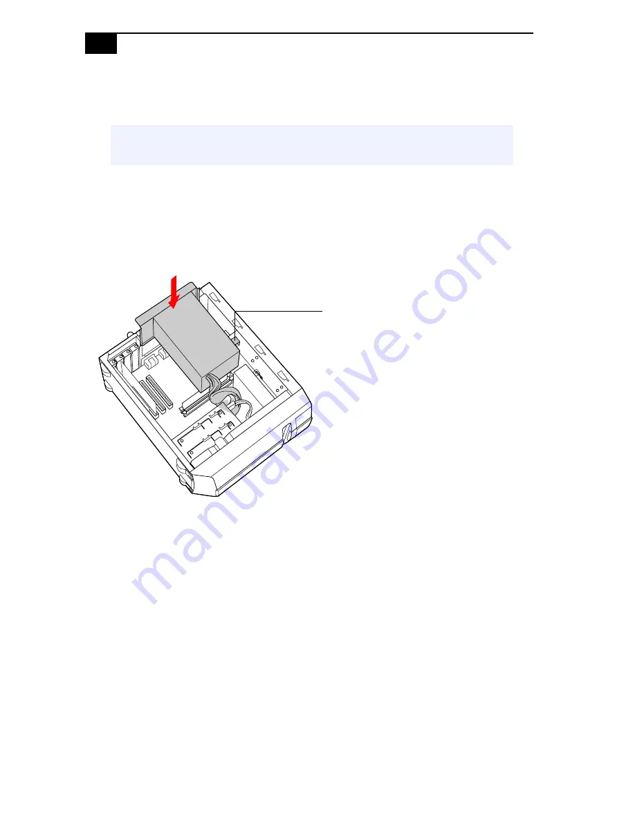
7
Replace the power supply by sliding it down the rails on each side of
the chassis opening until the metal tab on the power supply slips into
the slot in the CD-RW/DVD combo drive.
8
Replace the side panel (see
“Replacing the Side Panel”
on page 25).
9
Reconnect the power cord, and turn on the computer.
Your computer automatically recognizes any change in memory and will
configure itself accordingly when you turn on the computer. No further
action is required.
!
Touch any exposed metal part of the chassis to discharge static
electricity in your body before handling the memory module.
Tab fits into slot in
CD-RW/DVD combo drive
Содержание PCV-J200 - Vaio Desktop Computer
Страница 1: ......
Страница 14: ...VAIO System Reference Manual 2 Front View Front panel ...
Страница 26: ...VAIO System Reference Manual 14 ...
Страница 31: ...Configuring Your System 19 6 Click the Hibernate tab 7 Select the desired settings and then click OK ...
Страница 59: ...System Board 47 Floppy Disk Drive Connector 34 2 1 33 Key pin 5 ...
Страница 74: ...VAIO System Reference Manual 62 ...
Страница 76: ...VAIO System Reference Manual 64 ...
Страница 94: ...VAIO System Reference Manual 82 ...


