48
Pin No.
Pin Name
I/O
Description
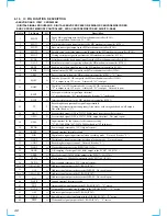
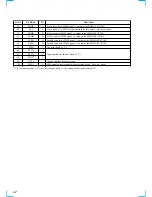
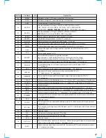
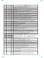
78
ILLIN
I
Auto dimmer control illumination line detection signal input terminal
“H” is input at dimmer detection Not used (fixed at “L”)
79
TELATT
I
Telephone detection signal input terminal At input of “H”, the signal is attenuated by –20 dB
80
NCO
O
Not used (open)
81
TEST IN
I
Setting terminal for the test mode “L”: test mode, Normally: fixed at “H”
82
ACC IN
I
Accessory detection signal input terminal “L”: accessory on
83
NCO
O
Not used (open)
84
LOCKIN
I
Mini-disc lock detection signal input from the MD mechanism controller (IC501) “H”: lock
85
RCIN1
I
Rotary remote commander shift key input terminal “L”: shift
86
HSTX
I
Hardware standby input terminal “L”: hardware standby mode Reset signal input in this set
87
MD2
I
Setting terminal for the CPU operational mode (fixed at “L” in this set)
88
MD1
I
Setting terminal for the CPU operational mode (fixed at “H” in this set)
89
MD0
I
Setting terminal for the CPU operational mode (fixed at “H” in this set)
90
RSTX
I
System reset signal input from the reset signal generator (IC652) and reset switch (SW503)
“L”: reset “L” is input for several 100 msec after power on, then it changes to “H”
91
VSS
—
Ground terminal
92
X0
I
Main system clock input terminal (3.68 MHz)
93
X1
O
Main system clock output terminal (3.68 MHz)
94
VCC
—
Power supply terminal (+5V)
95 to 97
NCO
O
Not used (open)
98
DIM SEL
I
Setting terminal for the dimmer “L”: dimmer in, “H”: no dimmer (fixed at “L” in this set)
99
TAP CD
I
Setting terminal for the internal mechanism tape or CD
“L”: CD, “H”: tape (fixed at “L” in this set)
100, 101
NCO
O
Not used (open)
102
AMTL IN
I
Auto metal detection signal input terminal “L”: auto metal Not used (open)
103
AMS IN
I
Input terminal of whether a music is present or not is detected at auto music sensor
“L”: music is present, “H”: music is not present Not used (open)
104
REEL
I
Rotation detect signal input terminal Not used (open)
105
POS0
I
106
POS1
I
107
POS2
I
108
POS3
I
109
LM EJ
O
Loading motor control signal output terminal “H” active
(For the eject direction and reverse side operation) Not used (open)
110
LM LD
O
Loading motor control signal output terminal “H” active
(For the loading direction and forward side operation) Not used (open)
111
CM ON
O
Capstan/reel motor control signal output terminal “H”: motor on Not used (open)
112
TAPON
O
Tape system power supply on/off control signal output terminal “H”: tape on Not used (open)
113
N ROUT
O
Forward/reverse direction control signal output terminal
“L”: forward direction, “H”: reverse direction Not used (open)
114
AMSON
O
Tape auto music sensor control signal output terminal
“L” is output to lower the gain for audio level at FF/REW mode Not used (open)
115
MTLON
I/O
METAL control in/out terminal
At initial mode: auto/manual mode selection input of METAL function (manual at “L” input)
At manual mode: METAL on/off control signal output terminal (METAL on at “H” output)
Not used this function (open)
116
DOLON
I/O
Dolby control in/out terminal
At initial mode: valid/invalid selection input of dolby function (valid at “L” input)
At normal mode: dolby on/off control signal output terminal (dolby on at “H” output)
Not used this function (open)
Tape position (EJECT/FF/REW/REV/
FWD mode) detect input from the tape
operation switch on the deck mechanism
Not used this function (open)
POS0: “L”: EJECT mode, “H”: others mode
POS1: “L”: FF and FWD mode, “H”: others mode
POS2: “L”: REW mode, “H”: others mode
POS3: “L”: REV and EJECT mode, “H”: others mode
Содержание MDX-C6500RV
Страница 4: ...4 ...
Страница 5: ...5 ...
Страница 6: ...6 ...
Страница 7: ...7 ...
Страница 8: ...8 ...
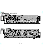
Страница 32: ...MDX C6500RV 32 32 4 15 PRINTED WIRING BOARD SUB Board See page 21 for Circuit Boards Location Page 27 Page 34 ...
Страница 33: ...MDX C6500RV 33 33 4 16 SCHEMATIC DIAGRAM SUB Board Page 30 ...
Страница 63: ...63 MDX C6500RV MEMO ...

