


20
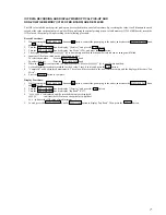
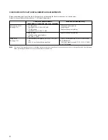
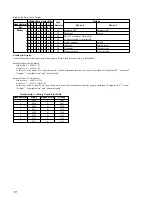
4-6. FUNCTIONS OF OTHER BUTTONS
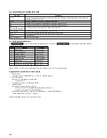
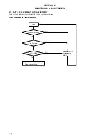
4-7. TEST MODE DISPLAYS
The DISPLAY/CHAR button is used to change the display mode. Each time the DISPLAY/CHAR button is pressed, the display changes
in the following order.
When C-PLAY or C-REC starts, the display is forcibly switched to one of “2” as the initial mode.
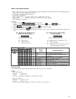
Supplementary explanations of each display
1.
Mode display
A display such as “TEMP ADJUST” or “CPLAY 1 MODE” appears.
2.
Error rate display
The error rate is displayed as shown below.
C=xxxxAD=xx
C= indicates C1 error, AD= indicates ADER.
3.
Address display
The address is displayed as shown below.
h=xxxx s=xxxx (pit of recordable disc and playback-only disc)
h=xxxx a=xxxx (groove of recordable disc)
h= indicates header address, s= indicates SUBQ address, a= indicates ADIP address.
* If the address cannot be read, “-” appears.
Displays other than the above are not used for service.
Contents
Sets continuous playback when pressed in the STOP state. When pressed during continuous playback, the
tracking servo turns ON/OFF.
Stops continuous playback and continuous recording.
The sled moves to the outer circumference only when this is pressed.
The sled moves to the inner circumference only when this is pressed.
Switches between the pit and groove modes when pressed.
Switches the spindle servo mode (CLV-S
y
CLV-A).
Switches the displayed contents each time the button is pressed
Ejects the disc
Releases the test mode
Function
PLAY
STOP
FF
FR
REC MODE
(other models/SF EDIT/SCROLL)
PLAY MODE
DISPLAY
EJECT
POWER/REPEAT
Order
1
2
3
4
5
6
7
8
Details
Mode display
Error rate display
Address display
Auto gain display
Detrack display
IVR display
Display of C1 error and jitter
Display of AD error and jitter
Display
CPLAY (xxxx
C=xxxxAD=xx
hxxxx sxxxx
AG=xx/xx[xx]
ADR=xx#0000
[xx][xx][xx]
Jxxxx Cxxxx
Jxxxx AD=xx
Содержание MDS-JB940
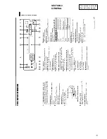
Страница 11: ...11 SECTION 2 GENERAL This section is extracted from instruction manual ...
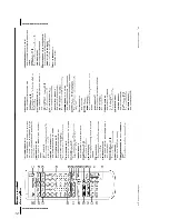
Страница 12: ...12 ...
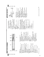
Страница 13: ...13 ...
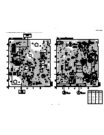
Страница 45: ...MDS JB940 45 45 6 17 SCHEMATIC DIAGRAM PANEL Section Page 39 ...
Страница 46: ...MDS JB940 46 46 6 18 SCHEMATIC DIAGRAM AC Board IC902 Page 40 Page 40 Page 40 ...


