


KZ-32TS1E(AEP) 2-2
7. Repeat step 1 and 3 to 5 described above until the detection set value is
obtained.
2-1-3. Component input adjustment
1.
Input All white 90 IRE signal of 1080/60i to the component input ter-
minal.
2.
Set Picture Mode into “LIVE”. Turn off “Dynamic pict”.
(Caution) The order of 1, 2 must not be changed.
3.
Select YUV Calibration from the AD Converter menu.
4.
Adjust the Sub Contrast (YUV) and then, adjust the detection values of
G to the set value.
Detection set value: 230
±
2
5.
Set the component input signal to All gray 20 IRE signal of 1080/60i .
6.
Adjust the Sub Bright (YUV) and then, adjust the detection values of G
to the set value.
Detection set value: 51
±
2
7.
Adjust the CB Offset (YUV) and then, adjust so that the detection value
of B is the same as G value.
8.
Adjust the CR Offset (YUV) and then, adjust so that the detection value
of R is the same as G value.
9.
Repeat step 5 to 7 until the detection set value in step 5 above is ob-
tained.
10. Repeat step 1 and 4 to 10 until the detection set value in steps 4 and 6
above are obtained.
2-1-4. Video input adjustment
1.
Input All white 90 IRE signal of NTSC to the video input terminal.
2.
Set Picture Mode into “LIVE”. Turn off “Dynamic pict”.
(Caution) The order of 1, 2 must not be changed.
3.
Select Video Calibration from the AD Converter menu.
4.
Adjust the Sub Contrast (Video) and then, adjust the detection values of
G to the set value.
Detection set value: 230 ± 2
5.
Set the video input signal to All gray 20 IRE signal of NTSC.
6.
Adjust the Sub Bright (Video) and then, adjust the detection values of
G to the set value.
Detection set value: 51 ± 2
7.
Adjust the CB Offset (Video) and then, adjust so that the detection
value of B is the same as G value.
Содержание KZ-32TS1E
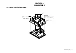
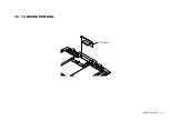
Страница 10: ...KZ 32TS1E AEP 1 6 1 6 TU BOARD REMOVAL 1 TU board ...
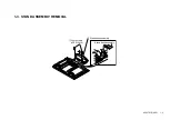
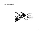
Страница 11: ...KZ 32TS1E AEP 1 7 1 7 H1 BOARD REMOVAL 2 Two screws BVTP 3x12 1 Screw BVTP 3x12 4 H1 board 3 H1 earth plate ...
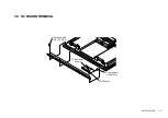
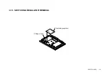
Страница 14: ...KZ 32TS1E AEP 1 10 1 10 SWITCHING REGULATOR REMOVAL 1 Support pcb 2 Switching regurator ...
Страница 24: ...KZ 32TS1E AEP 3 5 H2 H1 TU Q B 3 2 CIRCUIT BOARDS LOCATION ...
Страница 113: ...KZ 32TS1E AEP 113 9 978 727 01 English 2002EL08 Data Made in Japan 2002 5 ...


