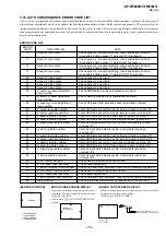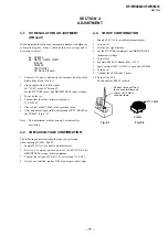
– 78 –
KP-FW46M31/FW51M31
RM-1015
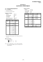
5-1. Picture Quality Adjustment
5-1-1. Preparation
1. Set in the service mode.
2. Set respective items as follows.
Adjustment Condition
DRC-MF
: DRC1250
PICTURE MODE
: HI-FINE
3D-NR MODE
: OFF
ECO MODE
: OFF
Main Picture adjustment : TWIN OFF
Sub Picture adjustment
: TWIN
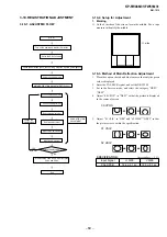
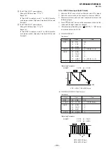
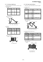
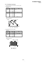
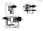
3. Connect the oscilloscope probe to the following point on the
UG board.
Measurement Point
UG Board CN1504 :
pin
G
t
VG
pin
B
t
VB
Note : After the adjustment 5-3. Picture Quality Adjustment,
these adjustment parameters must be recovered to the
original condition.
SECTION 5
ELECTRICAL ADJUSTMENTS
A5
B5
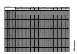
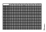
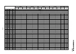
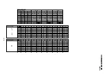
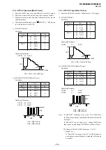
Category
Item
Data
PIC
00
PIC
100
01
COL
50
05
PIOF
0
LUMA
01
GAMM
0
06
BLK
0
COLR
00
CLOF
3
01
HUOF
3
02
RDRV
31
03
GDRV
31
04
BDRV
31
05
RCUT
31
06
GCUT
31
07
BCUT
31
09
DCOL
0
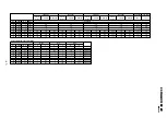
Category
Item
Data
PIC
00
PIC
60 (HI-FINE)
01
COL
50 (HI-FINE)
05
PIOF
5 (HI-FINE)
LUMA
01
GAMM
6 (HI-FINE)
06
BLK
0 (HI-FINE)
COLR
00
CLOF
0
01
HUOF
3
03
GDRV
35
06
GCUT
31
09
DCOL
3
MCP
14
ABLT
7 (Normal/V-comp)
0 other
MID2
02
BCOL
5 (TWIN)
Original Condition
DRC-MF
: DRC1250
ICTURE MODE : HI-FINE
3D-NR MODE
: OFF
ECO MODE
: OFF

