


20
GB
KLV-40/32/26U25xx
3-216-582-
31
(0)
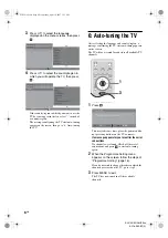
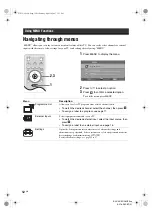
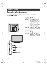
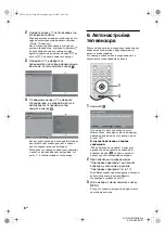
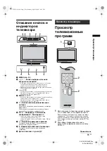
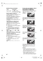
Viewing pictures from
connected equipment
Switch on the connected equipment, then
perform one of the following operation.
For equipment connected to the scart sockets using a
fully-wired 21-pin scart lead
Start playback on the connected equipment.
The picture from the connected equipment appears on
the screen.
For an auto-tuned VCR (page 4)
In TV mode, press PROG +/-, or the number buttons,
to select the video channel.
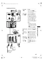
For other connected equipment
Press
/
repeatedly until the correct input
symbol (see below) appears on the screen.
Additional operations
AV1/
AV1, AV2/
AV2:
Audio/video or RGB input signal through the scart
socket
/
1 or 2.
appears only if an RGB
source has been connected.
AV3:
Component input signal through the Y, P
B
/C
B
, P
R
/C
R
sockets
/
3, and audio input signal through the
L, R sockets
/
3.
AV4/
AV4:
Video input signal through the video socket
4, and
audio input signal through the L (MONO), R audio
sockets
4.
appears only if the equipment is
connected to the S video socket
4 instead of the
video socket
4, and S video input signal is input
through the S video socket
4.
5:
RGB input signal through the PC connectors
5, and
audio input signal through the socket
.
AV6/
AV7:
Digital audio/video signal is input through the HDMI IN
6, 7 socket. Audio input signal is analogue only if the
equipment has been connected using the DVI and audio
out socket.
To
Do this
Return to the normal
TV operation
Press .
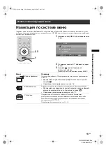
Access the Input
signal index table
Press
to access the Input signal
index table. (Then, only in
TV
mode, press
g
.) To select an input
source, press
F
/
f
, then press
.
To
Do this
010COV.book Page 20 Wednesday, April 18, 2007 3:53 PM


