- 10 -
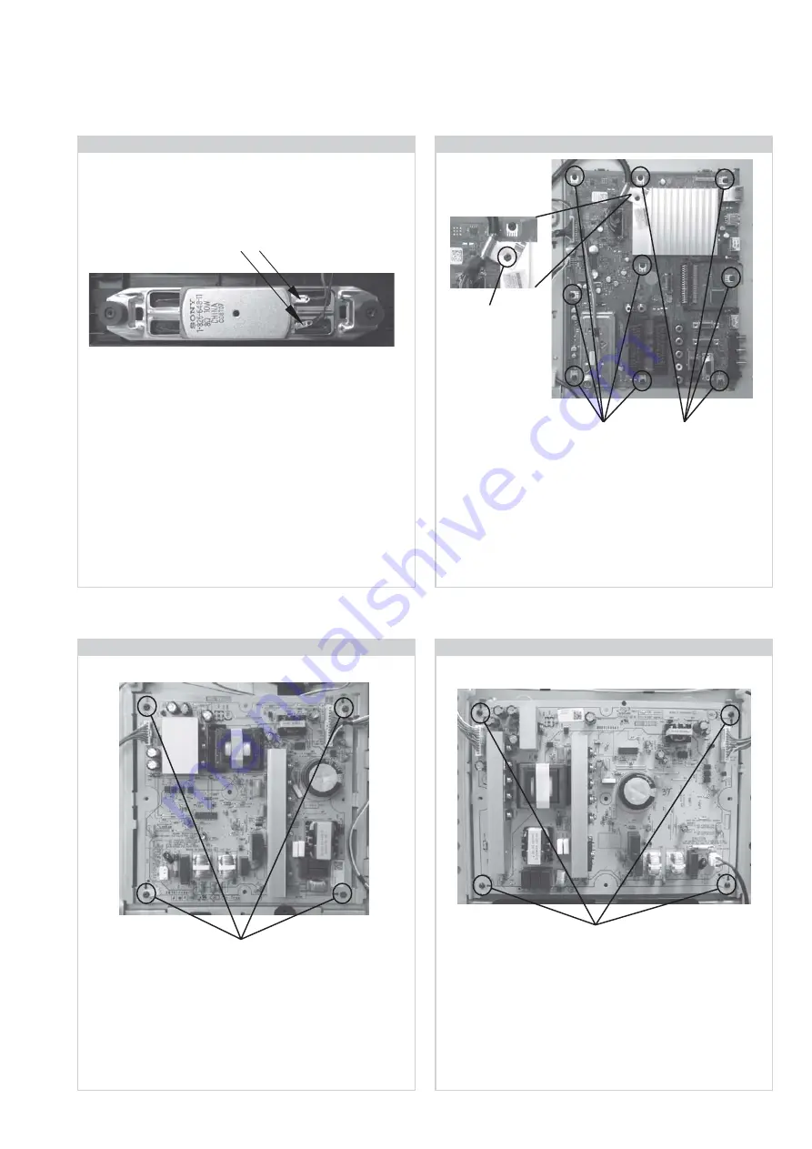
2-6. BA Board Removal
To remove the ‘BA’ board remove the 1 screw securing the
cable clip, disconnect all connectors and then remove the 9
screws circled and ease the board gently away from the back
of the TV set.
Screws
Screws
Screw Part number(s) and Description(s)
2-580-629-01 SCREW, +BVST 3X8
Screw
(Part No. 2-580-590-01)
Connectors
2-5. Loudspeaker Removal
To remove the ‘Loudspeaker’ first remove the ‘Rear Cover’
(See Sec 2-2-1). Disconnect the ‘Loudspeaker’ connectors and
pull the ‘Loudspeaker’ gently away from the back of the TV set.
2-8. G4 Board Removal (37 inches)
Screw Part number(s) and Description(s)
2-580-629-01 SCREW, +BVST 3X8
To remove the ‘G4’ board disconnect all the connectors and
remove the 4 screws circled, then ease the board gently away
from the back of the TV set.
Screws
2-7. G2 Board Removal (32 inches)
To remove the ‘G2’ board disconnect all the connectors and
remove the 4 screws circled, then ease the board gently away
from the back of the TV set.
Screw Part number(s) and Description(s)
2-580-629-01 SCREW, +BVST 3X8
Screws
www.freeservicemanuals.info
4/3/16
Published in Heiloo, Holland.


