background image

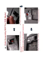
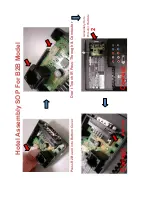
Hotel

A

ssembly SOP For B2B Model

In

sert Wire in

to R2 Bo

ard

Fix T

op Cover to

 Hotel Assy

 ( No  

need

 to use a screw )

Finished

Содержание KDL-32EX500 - Bravia Ex Series Lcd Television
Страница 1: ...are applicable at this time 2 0 2 2010 Amend 32 P 42 37 P 45 EX504 BAL board part number 3 0 5 2010 Add updated Panel Caution Note P 6 Add Inverter and Tcon Board Part Numbers P 42 45 48 51 54 Add illustration showing location of neck to base screws P 43 46 49 52 55 Add Support Panel Part Numbers P 41 44 47 50 53 4 0 6 2010 Add Hotel Assy to Exploded Views P 41 44 47 50 53 Add Hotel Addendum for B...

Страница 2: ...KDL 32 37 40 46 55EX500 Series AEP UK SERVICE MANUAL LCD Digital Color TV AZ1 L CHASSIS Segment 3a 1 9 888 265 04 ...

Страница 3: ...35 AEP KDL 3 7 E X 5 0 3 Black RM ED035 UK KDL 3 7 E X 5 0 4 Black RM ED035 AEP KDL 3 7 E X 5 0 5 Black RM ED035 AEP KDL 4 0 E X 5 0 0 Black RM ED035 AEP KDL 4 0 E X 5 0 1 Black RM ED035 AEP KDL 4 0 E X 5 0 3 Black RM ED035 UK KDL 4 0 E X 5 0 5 Black RM ED035 AEP KDL 4 0 E X 5 0 8 Black RM ED033 AEP KDL 4 6 E X 5 0 0 Black RM ED035 AEP KDL 4 6 E X 5 0 1 Black RM ED035 AEP KDL 4 6 E X 5 0 3 Black R...

Страница 4: ...follow these guidelines to protect your property and avoid causing serious injury Carry the TV with an adequate number of people larger size TVs require two or more people Correct hand placement while carrying the TV is very important for safety and to avoid damages SAFETY RELATED COMPONENT WARNING Components identified by shading and mark on the schematic diagrams exploded views and in the parts ...

Страница 5: ...porté par au moins deux personnes Lors du transport du téléviseur l emplacement des mains est très important pour votre sécurité ainsi que pour éviter de causer des dommages ALERTE Afi n d eviter tout risque d electrocution provenant d un chassis sous tension un transformateur d isolement doit etre utilise lors de tout depannage Le chassis de ce recepteur est directement raccorde a l alimentation ...

Страница 6: ...es or in areas of high humidity for an extended period of time 4 Do not expose the LCD panel to direct sunlight 5 Avoid contact with water It may cause a short circuit within the module 6 Disconnect the AC power when replacing the backlight CCFL or inverter circuit High voltage occurs at the inverter circuit at 650Vrms 7 Always clean the LCD panel with a soft cloth material 8 Use care when handlin...

Страница 7: ...d Be absolutely certain that you have replaced all the insulators 4 Look for unauthorized replacement parts particularly transistors that were installed during a previous repair Point them out to the customer and recommend their replacement 5 Look for parts which though functioning show obvious signs of deterioration Point them out to the customer and recommend their replacement 6 Check the line c...

Страница 8: ...eters must have an accurate low voltage scale The Simpson s 250 and Sanwa SH 63TRD are examples of passive VOMs that are suitable Nearly all battery operated digital multimeters that have a 2 VAC range are suitable see Figure A How to Find a Good Earth Ground A cold water pipe is a guaranteed earth ground the cover plate retaining screw on most AC outlet boxes is also at earth ground If the retain...

Страница 9: ...blem A definition of the STANDBY LED flash indicators is listed in the instruction manual for the user s knowledge and reference If an error symptom cannot be reproduced the remote commander can be used to review the failure occurrence data stored in memory to reveal past problems and how often these problems occur STBY LED Flash time Service menu Item name Screen Display Diagnostic Item Descripti...

Страница 10: ... DISPLAY For errors with symptoms such as power sometimes shuts off or screen sometimes goes out that cannot be confirmed it is possible to bring up past occurrences of failure for confirmation on the screen To Bring Up Screen Test In standby mode press buttons on the remote commander sequentially in rapid succession as shown below ...

Страница 11: ...0 0 0 0 0 0 0 0 0 0 0 0 0 0 0 0 0 0 0 0 0 0 0 0 0 0 0 0 0 0 0 0 0 0 0 0 0 0 0 0 0 0 0 0 0 0 0 0 0 0 0 0 SELF CHECK 1 0 0 2 M A I N P 0 0 3 DC_ A LER T 1 0 0 4 DC_ A LER T 2 0 0 6 BL 0 0 7 TEMP 0 0 9 FAN 1 2 3 4 5 0 0 3 3 3 0 6 7 8 9 1 N E X T P A G E Error count 00 99 Error history Last failure time beforehand Error history Failure time before last Error history The last failure time Item name STB...

Страница 12: ...ter you have completed the repairs clear the result display to 0 Clearing the Self Check Diagnostic List 1 Error history and Error count Press the Channel 8 Channel 0 2 Panel operation time Press the Channel 7 Channel 0 Exiting the Self diagnostic screen To exit the Self Diagnostic screen turn off the power to the TV by pressing the POWER button on the remote or the POWER button on the TV ...

Страница 13: ... UK 13 SEC 1 DISASSEMBLY KDL 32EX500 Series KDL 32EX500 Series 1 1 M O V I E L I S T KDL 37EX500 Series KDL 37EX500 Series KDL 40EX500 Series KDL 40EX500 Series KDL 46EX500 Series KDL 46EX500 Series KDL 55EX500 Series KDL 55EX500 Series ...

Страница 14: ...f all when you enter Service Mode you can see Digital service mode Whenever you press OPTIONS or JUMP on remote each service mode is changed Digital Chassis Sub DIGITAL SERVICE 001 OP 000 VERS MAIN SUB DM1 301J00AA SM1 010W00AA M2 105C SB1 000W00AA DD1 016J00AA SD1 010W00AA DM1 301J00AA RF01 05 WP00 521J00AA ID1C117081 ID1C117081 LTY320AB01 PID04020000 WF 2 0 0 99 BEM WF 0B BM1 012W00LU Camera FW ...

Страница 15: ... service mode then turn off the power switch Test TV Display 5 Vol Up Power Service mode on Other Power off on Service mode off Jump Option Mute 0 10 or 0 9 0 8 Mute 0 3 6 2 5 1 4 The flow of control Change module Write data Execute Read data Test reset Data up down Category up down Item up down Function ...

Страница 16: ... and advance next step When returning on the previous page press return d Change data by number key 0 9 directly 0 255 e Press 12 enter select to save data It shows red WRITE It indicate writing is processing f Writing process is done at this point DIGITAL SERVICE 006 WB 000 WHITE_BALANCE ___ DIGITAL SERVICE WB 1 R_DRV 128 2 G_DRV 128 3 B_DRV 128 4 R_BKG 128 5 G_BKG 128 6 B_BKG 128 Please input WB...

Страница 17: ... Mute on remote It shows green SERVICE changes to green WRITE b Press 0 or enter on remote Green WRITE changes to red WRITE It indicate writing is processing c After a while red WRITE changes to green SERVICE Writing process is done at this point 3 TV reboot is necessary for applying data change CHASSIS WRITE 000 CXD2813R 000 H_DET_NOSIG_CNT 1 A D JUSTMENT ...

Страница 18: ... A_NOSIG_DET 001 DIGITAL SERVICE 003 DIG_SRV_MODE 000 TEST_PATTERN DIGITAL DIG_SRV_MODE SERVICE TEST_PATTERN 1 Video 2 Audio 2 Change Data of Digital service mode 003 DIG_SRV_MODE category 003 DIG_SRV_MODE is one category of Digital service mode Please note because this operation is special a Press 2 5 on remote to select 003 DIG_SRV_MODE b Press 1 4 on remote to select up down Item c Press 0 10 o...

Страница 19: ...ng segment or destination information in Product ID When the wrong setting is written TV may not operate 000 SEG nnnProduct ID segment information 001 DESTnnnProduct ID destination information a Change data for each model b Press 0 or enter on remote It shows red WRITE It indicate writing is processing c Writing process is done at this point DIGITAL SERVICE 002 MODEL 000 SEG 01 2a 3 Write ...

Страница 20: ...ST Press mute on remote Added green EXE after green RST d Press 0 or enter on remote Green EXE RST changes to red EXE RST It indicate writing is processing After a while red EXE RST changes to green SERVICE And all LED lights Writing process is done at this point Another way You can set to shipping condition w o entering Service Mode Cursor Up on remote Power Key on Front panel TIMER Standby POWER...

Страница 21: ... 5 6 7 No Green Power LED Dead Set Stationary colored lines or dots No video one of Inputs No video all Inputs No Remote Wireless can t connect No Audio BAL BOARD G BOARD HLR BOARD WiFi MODULE D1 BOARD LVDS CABLE LCD PANEL Problem POWER POWER DTT AUDIO POWER PANEL TCON PANEL INVERTER TEMP doubtful part Few possibility Reference Symptoms Shutdown Power LED blinking red diagnostics sequences Video m...

Страница 22: ... TV is switched on Is the Standby Led blink Is the Picture and Sound OK Do the buttons on the TV Remote Commander work properly END See No Power See Standby LED Blink See No Picture No Sound See TV Commander button malfunction Is the network connection OK See Can t connect network No Yes No Yes No Yes No Yes No Yes ...

Страница 23: ...37 40 46 55EX500 Series AEP UK 23 TROUBLE SHOOTING 3 3 N O P OWER No Power Check STBY 3 3V at 1 pin of CN3800 on the BAL Board Harness G Board Replace Between G Board to BAL Board Harness BAL Board NG OK NG OK ...

Страница 24: ... times blinkings Main Power Error TROUBLE SHOOTING 3 4 S T A N D B Y L E D B L I N K 2 times Blinkings Check REG12V at pins 6 7 of CN3800 on the BAL Board BAL Board Harness G Board Replace Between G Board to BAL Board Harness 12V NG 12V OK NG OK ...

Страница 25: ...c BAL Board Speaker Check 5V_MAIN at JL3731 or JL3732 on the BAL Board Check Speaker Impedance at SP Connector F3701 IC3701 etc BAL Board Check X_ASW_PROTECT at pin 29 of IC5000 on the BAL Board Check 12 5V at pin 2 of CN3800 on the BAL Board G Board Check 12 5V_AU1 at F4200 on the BAL Board F4200 IC4200 etc BAL Board IC9000 etc BAL Board DC_ALERT NG OK AUDIO AUDIO FE BE Communication NG OK NG OK ...

Страница 26: ...KDL 32 37 40 46 55EX500 Series AEP UK 26 TROUBLE SHOOTING 3 4 times blinkings Balancer Error 4 times Blinkings Check PANEL_FAIL at JL2565 on the BAL Board BAL Board PANEL Balancer Between 0 84V to 2 65V ...

Страница 27: ...OTING 4 5 times blinkings T con Error 5 times Blinkings Check PANEL_VCC at JL3806 on the BAL Board G Board Between G to Panel harness check LVDS Harness check Panel T con change BAL Board Harness LVDS Harness Panel T con about 12V NG OK NG OK NG OK NG OK ...

Страница 28: ... OK Temperature Ventilation etc BAL Board Set to another Location etc Change BAL Board and Aging a few hours Panel 5 6 times blinkings Backlight Error 6 times Blinkings Check PANEL_FAIL at JL2565 on the BAL Board G Board BAL Board Under 2 65V Change D1 Board Inverter D1 Board Change G Board Panel T con NG OK NG OK NO YES NG OK Over 2 65V ...

Страница 29: ...splayed BAL Board Replace the LVDS Harness LCD Panel T con Harness LVDS Check BL_ON at JL2566 on the BAL Board BL_ON H BAL Board Check Harness Between G Board to BAL Board Harness G to BAL BL_ON not H Change BAL Board G Board NO YES NG OK NG OK NG OK PANEL_VCC At JL3806 on the BAL Board G Board YES NO about 12V ...

Страница 30: ...eries AEP UK 30 TROUBLE SHOOTING 3 6 N O S O U N D No Sound Check the Speaker Harness Speaker Harness Replace the BAL Board BAL Board Speaker NG OK NG OK Check the Speakers setting Change to TV Speaker Audio System TV Speakers ...

Страница 31: ...500 Series AEP UK 31 3 7 TV COMMANDER BUTTONS MALFUNCTION TROUBLE SHOOTING 1 TV button malfunction Button malfunction on the TV BAL to Switch Unit harness check Switch Unit Harness Switch Unit change BAL Board OK NG OK NG ...

Страница 32: ...e commander Green LED light at power indicator OK NG Sensor is broken HLR Board BAL Board OK NG Mechanical ex bezel Green LED blinks at power indicator when using commander near sensor s window Check the Harness between the BAL Board and the HLR Board Exchange the Harness Exchange the HLR Board Harness OK NG OK OK NG NG ...

Страница 33: ...sult Local Access Ether net cable Connection result Cable Connection BAL Board OK NG OK NG Connection result Internet Access Proxy setting NG 2 USB Wireless Network malfunction Wireless Network on the TV Is the radio field Strength too weak or even No signal Access Point BAL Board Error Message appear when the Wireless Network is selected USB Dongle NO YES NO YES ...

Страница 34: ...KDL 32 37 40 46 55EX500 Series AEP UK 34 SEC 4 DIAGRAMS 4 1 B L OCK DIAGRAM ...

Страница 35: ...KDL 32 37 40 46 55EX500 Series AEP UK 35 D I A G R A MS 4 2 C I RCUIT BOARDS LOCATION 1 KDL 32EX500 Series BAL Board Speaker L HLR Board Speaker R Switch Unit Inverter G2ME Board T CON ...

Страница 36: ...KDL 32 37 40 46 55EX500 Series AEP UK 36 D I A G R A MS 2 KDL 37EX500 Series BAL Board Speaker L HLR Board Speaker R Switch Unit Inverter G2HE Board T CON ...

Страница 37: ...KDL 32 37 40 46 55EX500 Series AEP UK 37 D I A G R A MS 3 KDL 40EX500 Series BAL Board Speaker L HLR Board Speaker R Switch Unit Inverter G2HE Board T CON ...

Страница 38: ...KDL 32 37 40 46 55EX500 Series AEP UK 38 D I A G R A MS 4 KDL 46EX500 Series BAL Board Speaker L HLR Board Speaker R Switch Unit Inverter GD2 Board T CON ...

Страница 39: ...KDL 32 37 40 46 55EX500 Series AEP UK 39 D I A G R A MS 5 KDL 55EX500 Series BAL Board Speaker L HLR Board Speaker R Switch Unit Inverter G5E Board T CON D1Board ...

Страница 40: ...are not stocked because they are seldom required for roution service The construction parts of an assembled part are indicated with a collation number in the remark colum Items marked are not stocked since they are seldom required for routine service Some delay should be anticipated when ordering these items ...

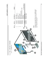
Страница 41: ...8 11 SWITCH UNIT 5 4 166 124 11 COVER UNDER 32 6 4 158 349 01 NECK M3 7 X 2546 541 1 COVER M3 ASSY 8 X 2546 980 1 BASE M3 ASSY 9 X 2546 624 1 REAR COVER TR32 ASSY X 2547 420 1 REAR COVER 32_SAT ASSY EX505 508 10 3 106 546 51 COVER ECS HOTEL ASSY See Hotel Addendum 11 4 167 326 01 BRACKET VESA S 11a 4 166 118 11 SUPPORT PANEL 11a Note Whenever removing the Rear Cover on B2B models remember to remov...

Страница 42: ...1 BEZEL ASSY 32TR_BCK EX501 EX508 13 A 1753 636 A HLR MOUNT 14 4 166 268 01 BRACKET SIDE JACK 15 1 811 054 11 LCD PANEL S32TDP 16 1 474 201 21 STATIC CONVERTER TV 17 A 1760 331 A BAL BOARD COMPLETE EX500 501 A 1768 994 A BAL BOARD COMPLETE EX503 A 1769 581 A BAL BOARD COMPLETE EX505 508 A 1780 319 A BAL BOARD COMPLETE EX504 18 1 837 454 11 POWER SUPPLY CORD 19 1 857 634 11 INVERTER BOARD 20 1 489 ...

Страница 43: ...1 3 SCREWS 5 1 K D L 3 2 E X 5 0 0 S E R I E S PART No DESCRIPTION 2 580 640 01 SCREW BVTP 4X16 TYPE2 IT 3 2 580 595 01 SCREW PSW M3X12 7 685 648 79 SCREW BVTP 3X12 TYPE2 IT 3 2 580 608 01 SCREW PSW M5X16 2 580 592 01 SCREW PSW M3X8 4 159 298 01 SCREW PSW M4X10 ...

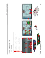
Страница 44: ...7 3 4 158 350 01 NECK ML3 4 X 2546 541 1 COVER M3 ASSY 5 X 2541 845 1 BASE ML3 ASSY 6 X 2546 655 1 REAR COVER TR37 ASSY X 2547 422 1 REAR COVER 37_SAT ASSY EX505 7 3 106 546 51 COVER ECS HOTEL ASSY See Hotel Addendum 8 4 167 326 01 BRACKET VESA S 8a 4 166 118 01 SUPPORT PANEL C Note Whenever removing the Rear Cover on B2B models remember to remove the connector inside the Hotel Assy on the R2 boar...

Страница 45: ...KET SIDE JACK 12 1 811 077 11 LCD PANEL A37V9 13 1 474 202 21 STATIC CONVERTER TV 14 A 1760 331 A BAL BOARD COMPLETE EX500 501 A 1768 994 A BAL BOARD COMPLETE EX503 A 1769 581 A BAL BOARD COMPLETE EX505 A 1780 319 A BAL BOARD COMPLETE EX504 15 1 837 454 11 POWER SUPPLY CORD 16 1 858 364 22 LOUDSPEAKER 12 5x4 5CM 17 4 166 121 11 BRACKET SP 37L 18 4 166 122 11 BRACKET SP 37R 19 1 857 701 11 INVERTER...

Страница 46: ...2 3 SCREWS 5 2 K D L 3 7 E X 5 0 0 S E R I E S PART No DESCRIPTION 2 580 640 01 SCREW BVTP 4X16 TYPE2 IT 3 2 580 595 01 SCREW PSW M3X12 7 685 648 79 SCREW BVTP 3X12 TYPE2 IT 3 2 580 608 01 SCREW PSW M5X16 2 580 592 01 SCREW PSW M3X8 4 159 298 01 SCREW PSW M4X10 ...

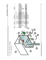
Страница 47: ... 4 158 350 01 NECK ML3 4 X 2546 541 1 COVER M3 ASSY 5 X 2541 845 1 BASE ML3 ASSY 6 X 2546 618 1 REAR COVER TR40 ASSY X 2547 412 1 REAR COVER TR40_SAT ASSY EX505 508 7 3 106 546 51 COVER ECS HOTEL ASSY See Hotel Addendum 8 4 167 326 01 BRACKET VESA S 8a 4 166 118 01 SUPPORT PANEL C Note Whenever removing the Rear Cover on B2B models remember to remove the connector inside the Hotel Assy on the R2 b...

Страница 48: ...OUNT 11 4 166 268 01 BRACKET SIDE JACK 12 1 811 055 12 LCD PANEL S40TDP 13 1 474 202 21 STATIC CONVERTER TV 14 A 1760 331 A BAL BOARD COMPLETE EX500 501 A 1768 994 A BAL BOARD COMPLETE EX503 A 1769 581 A BAL BOARD COMPLETE EX505 508 15 1 837 454 11 POWER SUPPLY CORD 1 837 455 11 POWER SUPPLY CORD UK EX503 16 1 858 364 22 LOUDSPEAKER 12 5x4 5CM 17 4 166 119 11 BRACKET SP 40L 18 4 166 120 11 BRACKET...

Страница 49: ...3 3 SCREWS 5 3 K D L 4 0 E X 5 0 0 S E R I E S PART No DESCRIPTION 2 580 640 01 SCREW BVTP 4X16 TYPE2 IT 3 2 580 595 01 SCREW PSW M3X12 7 685 648 79 SCREW BVTP 3X12 TYPE2 IT 3 2 580 608 01 SCREW PSW M5X16 2 580 592 01 SCREW PSW M3X8 4 159 298 01 SCREW PSW M4X10 ...

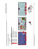
Страница 50: ...1 NECK ML3 4 X 2546 541 1 COVER M3 ASSY 5 X 2541 846 1 BASE L3 ASSY 6 X 2546 628 1 REAR COVER TR46 ASSY X 2547 418 1 REAR COVER 46_SAT ASSY EX505 7 3 106 546 51 COVER ECS HOTEL ASSY See Hotel Addendum 8 1 842 008 11 AC INLET FILTER 9 4 167 326 01 BRACKET VESA S 9a 4 166 118 01 SUPPORT PANEL C Note Whenever removing the Rear Cover on B2B models remember to remove the connector inside the Hotel Assy...

Страница 51: ...2 4 166 268 01 BRACKET SIDE JACK 13 1 811 056 12 LCD PANEL S46TDP 14 1 474 205 11 STATIC CONVERTER TV GD2 15 A 1760 331 A BAL BOARD COMPLETE EX500 501 A 1768 994 A BAL BOARD COMPLETE EX503 A 1769 581 A BAL BOARD COMPLETE EX505 16 1 837 639 11 POWER SUPPLY CORD EX500 501 505 1 837 640 11 POWER SUPPLY CORD EX503 17 1 858 371 11 LOUDSPEAKER 20x4 5CM 18 4 157 973 11 BRACKET SP 46L 19 4 157 974 11 BRAC...

Страница 52: ...5 0 0 S E R I E S PART No DESCRIPTION 2 580 640 01 SCREW BVTP 4X16 TYPE2 IT 3 2 580 595 01 SCREW PSW M3X12 7 685 648 79 SCREW BVTP 3X12 TYPE2 IT 3 2 580 608 01 SCREW PSW M5X16 2 580 592 01 SCREW PSW M3X8 4 159 298 01 SCREW PSW M4X10 2 580 629 01 SCREW BVST 3X8 4 167 964 01 SCREW PWTP2 4X16 ...

Страница 53: ...6 543 1 COVER LL3 ASSY 5 X 2541 847 1 BASE LL3 ASSY 6 X 2546 580 1 REAR COVER 55TR ASSY X 2547 421 1 REAR COVER 55 SAT ASSY EX505 7 3 106 546 51 COVER ECS HOTEL ASSY See Hotel Addendum 8 1 842 009 11 AC INLET FILTER 9 4 167 326 01 BRACKET VESA S 10 4 156 946 01 BRACKET VESA XL 10a 4 166 118 11 SUPPORT PANEL C Note Whenever removing the Rear Cover on B2B models remember to remove the connector insi...

Страница 54: ...8 01 BRACKET SIDE JACK 14 1 811 057 12 LCD PANEL S55TDP 15 1 474 203 11 STATIC CONVERTER TV 16 1 474 206 11 STATIC CONVERTER TV D1 17 A 1760 331 A BAL BOARD COMPLETE EX500 EX501 A 1768 994 A BAL BOARD COMPLETE EX503 A 1769 581 A BAL BOARD COMPLETE EX505 18 1 858 354 11 LOUDSPEAKER 19 1 837 639 11 POWER SUPPLY CORD EX500 501 505 1 837 640 11 POWER SUPPLY CORD EX503 20 1 857 653 11 INVERTER BOARD 21...

Страница 55: ... K D L 5 5 E X 5 0 0 S E R I E S PART No DESCRIPTION 2 580 640 01 SCREW BVTP 4X16 TYPE2 IT 3 2 580 595 01 SCREW PSW M3X12 7 685 648 79 SCREW BVTP 3X12 TYPE2 IT 3 2 580 608 01 SCREW PSW M5X16 2 580 592 01 SCREW PSW M3X8 4 159 298 01 SCREW PSW M4X10 2 580 629 01 SCREW BVST 3 8 ...

Страница 56: ...CTOR ASSY CN6301 CN6600 1 910 060 10 HARNESS ASSY CN2602 CN4300 CN001 SW SP 1 837 322 11 CONNECTOR ASSY CN6705 BALANCER 1 910 060 11 CONNECTOR ASSY 15P CN6401 CN2561 CN3800 1 837 324 11 CONNECTOR ASSY CN6704 BALANCER 1 910 060 12 CONNECTOR ASSY 14P CN6402 BALANCER 1 837 524 11 FLEXIBLE FLAT CABLE CN6200 TCON 1 910 060 13 CONNECTOR ASSY 6P CN6403 TCON 1 910 060 22 HARNESS ASSY 15P CN2602 CN3400 CN0...

Страница 57: ...487 700 11 REMOTE COMMANDER RM ED035 1 487 758 11 REMOTE COMMANDER RM ED033 EX508 5 6 4 MI SCELLANEO US 1 822 482 11 HDMI CONNECTOR REAR 1 822 580 41 CONNECTOR DUAL SCART 1 822 484 11 HDMI CONNECTOR SIDE 1 822 581 12 MULTIPLE PHONO JACK 4P 1 822 525 21 OPTICAL OUT CONNECTOR 1 842 010 11 JACK 1 821 827 21 D SUB CONNECTOR 1 822 524 21 PHONO JACK 2P 1 821 868 11 ETHERNET CONNECTOR 8P 1 842 096 11 PHO...

Страница 58: ...KDL 32 37 40 46 55EX500 Series AEP UK 58 END 9 888 265 04 English 10FP7100 1 Made in U K 2010 6 Sony Corporation Sony UK Service Promotions Dept ...

Страница 59: ...B Model Use a Gauge to Pull the Wire 1 910 057 37 to the Outside Use Fingers to Pull Wire to the Outside Paste ID Label onto R C First Ready For Hotel Assembly R2 Board Production line need to create pull gauge for operator use ...

Страница 60: ...Put R2 Board into bottom cover Tilt Angle Director to Bottom Cover Hotel Assembly SOP For B2B Model Fix VGA Screws 2 580 626 01 to R2 Board A 1565 554 A Finished Assembly ...

Страница 61: ...Hotel Assembly SOP For B2B Model Press R2 Board into Bottom Cover Don t Touch IR Pass Through Connector Assembly Hole Director Outside Align Hole Correct Correct 2 ...

Страница 62: ... B2B Model Wrong Hole Not Aligned Assembly Hole Director Inside Wrong Fix T3 Screw 2 Pcs 14mm To R C Part Number 7 685 649 79 T3 Screw different to Side Cover Use I O Attention The Screws are different to the side cover I O ...

Страница 63: ...Hotel Assembly SOP For B2B Model Insert Wire into R2 Board Fix Top Cover to Hotel Assy No need to use a screw Finished ...

Страница 64: ...Hotel Assembly SOP For B2B Model Separation Push The Top Cover Edge Use finger to Pull the Top Cover Edge Finished ...

Отзывы: