- 18 -
REMO
V
AL AND REPLA
CEMENT OF
THE MAIN
-
BRA
CKET
BO
TT
OM PLA
TES.
(1) REMO
VING
THE PLA
TES
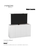
In the e
v
ent of servicing being required to the solder side of the
A Board printed wiring board, the
bottom plates fitted to the main chassis bracket require to be removed.
This is performed by cutting the gates with a sharp wire cutter at the locations indicated by the
arrows.
Note :
There are 3 plates fitted to the main bracket.
Only remove the necessary plate to gain access to the printed wiring board.
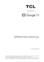
(2) REFITTING
THE PLA
TES
Because the plates differ in size it is important that the correct plates are refitted in their original
location.
Please note that the plates need to be rotated 180 degrees from their cut position to allow the tabs to
be fitted into their catch positions.
For safety reasons, on no account should the plates be re-
moved and not refitted after servicing.
Ta
b
Catch