Basic Settings with the Subdisplay
46
Chap
ter
3
Ba
s
ic
Ad
jus
tme
nt
s
an
d Set
tings
(700 mV), with ITU-R709 gamma (standard
gamma) and the input level as 100%.
Latitude values are displayed with E, showing the
latitude on the high luminance side as an f-stop
value, using a gray-scale chart with an 18%
reflection rate as the key light Gradations on the
low luminance side can be expressed up to
approximately –6.5 stop at 0 dB.
Note
As the dynamic range indication shows a value for the
input video, the dynamic range of the output video is
limited by the output settings as follows:
If a gamma other than S-LOG is selected
The upper limit is clipped according to the output
video limitation specified by the gamma setting.
When you select a curve as Hyper Gamma No. 4,
which compresses 460% input to 109%, the
output video is fed within the range up to 460% of
input video even if 800% is displayed on the
subdisplay as the dynamic range as the output
video is limited to 109%.
Using CvpFileEditor V4.0
, you can
change the dynamic range of Hyper Gamma and
create a user gamma curve having no dynamic
range limitation.
If the white clip function is in use
As the white clip function limits the level of
output video, the dynamic range specified for the
input video may not be obtained for video output.
Memo
Why the ISO sensitivity is defined for 20%
input
Defining the level of gray scale of 18% reflection rate for
the ISO sensitivity on the linear curve (defining with
input signal) permits you to use the values as the absolute
reference for proper gamma conversion in
postproduction.
In addition, defining the output for 20% input with ITU-
R709 so that it becomes the reference code for Cineon
curve allows high compatibility.
On this unit, you can adjust the compensation
data for the mounted lens in Custom mode and
registered it in the built-in memory as a lens file
(max. 64 files in total: 32 files for serial lenses
and another 32 files for non-serial lenses).
You can invoke the compensation data for the
mounted lens simply by selecting the
corresponding file.
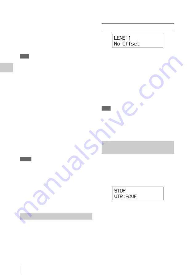
Lens file selection page
On the first line, select the number of a lens file.
(If a serial lens is mounted, the unit will recognize
the lens name and invoke the corresponding lens
file automatically. In that case, the file number is
always 33.)
The second line displays the lens file name
corresponding to the selected number.
The selected lens file is retained until a new lens
file is selected. As long as you are using the same
lens, you do not need to select it again.
Note
All the lens files are named “No Offset,” with all zero
settings at shipment. File registration and modification of
data in a lens file must be performed in Custom mode.
For details on the lens files, see Chapter 6 “Storage
and Retrieval of User Setting Data” (page 141).
You can check the operating status of the VTR
module in the subdisplay. When the unit is in
recording pause mode, you can also use this page
to switch the power supply to the VTR module
between power saving (SAVE) mode and standby
(STBY) mode.
The first line shows the operating status of the
VTR module (REC PAUSE, REC, F.FWD,
REW, PLAY, STOP, etc).
The second line shows the VTR module power
supply mode (SAVE, STBY) when it is in stop
mode (STOP), recording pause mode (REC
PAUSE), or playback pause mode (PLAY
PAUSE). Use an assignable button/switch to
which the VTR SAVE function is assigned to
select SAVE or STBY.
For details, see “Assigning Functions to Assignable
Buttons/Switch” (page 48).
Selecting a Lens File
Checking the Operating Status of
the VTR Module
Содержание HKSR-9003
Страница 176: ...Index 176 Index ...


