


15
HCD-RV660D/RV990D
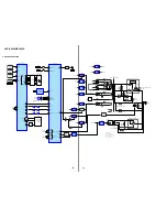
4. ELECTRICAL ADJUSTMENTS
VIDEO SECTION
oscilloscope
set
J802
VIDEO OUTPUT
75
Ω
1.00
±
0.05 Vp-p
(WHITE 100%)
Note:
1. VIDEO board is basically designed to operate without
adjustment. Therefore, check each item in order given.
2. Use DVD reference disc unless othermise indicated.
[DVD reference disc]
LUV-P01 (CD)
: PART No. 4-999-032-01
TDV-520CSO (DVD-SL) : PART No. J-2501-236-A
TDV-540C (DVD-DL)
: PART No. J-2501-235-A
Note:
Do not use exiting test disc for DVD.
3. Use an oscilloscope with more than 10M
Ω
impedance.
4. Clean the object lens by an applicator with neutral detergent
when the signal level is low than specified value with the
following checks.
AUTO SERVO ADJUSTMENT
After parts related to the servo circuit (RF amplifier (IC001), DSP
(IC509), motor driver (IC501), EEPROM (IC903) so on) are
replaced, re-adjusting the servo circuit is necessary. Select “ALL”
at “1. DRIVE AUTO ADJUSTMENT” (Refer to page 8 in TEST
MODE) and adjust DVD-SL (single layer), CD and DVD-DL (dual
layer).
Ver 1.3
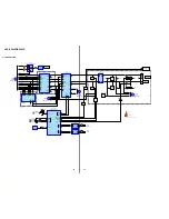
DECISION TO PASS OR FAIL OF THE OPTICAL
PICK-UP BLOCK
Connection:
Procedure:
1. Connect an oscilloscope to test point pin
1
and pin
3
of CN901
on the DMB03 board.
2. Turn the power on.
3. Put the disc (LUV-P01) (Part No.: 4-999-032-01) (CD) in to
playback.
4. Confirm that oscilloscope waveform is clear and check RF
signal level is correct or not.
5. Put the disc (TDV-520CSO) (Part No.: J-2501-236-A) (DVD) in
to playback.
6. Perform Comfirmation in the same manner as step 4.
Note:
A clear RF signal waveform means that the shape “
◊
” can be clearly
distinguished at the center of the waveform.
Video Level Check (VIDEO BOARD)
Purpose
This adjustment is made to satisfy the NTSC standard, and if not
adjusted correctly, the brightness will be too large or small.
Procedure:
1. Connect oscilloscope to VIDEO output.
2. Load a DVD reference disc playback.
3. Check the video signal level is 1.00
±
0.05Vp-p.
oscilloscope
+
DMB03 board
CN901 pin 1
–
CN901 pin 3
CD : 1.05
±
0.2 Vp-p
VOLT/DIV : 200 mV
TIME/DIV : 500 nS
DVD : 1.09
±
0.2 Vp-p
RF signal waveform
– DMB03 BOARD (SIDE A) –
CN901
1
7
Checking Location:
Содержание HCD-RV660D
Страница 5: ...5 HCD RV660D RV990D SECTION 1 GENERAL This section is extracted from instruction manual ...
Страница 6: ...6 HCD RV660D RV990D ...
Страница 88: ...88 HCD RV660D RV990D MEMO ...
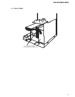
Страница 91: ...3 HCD RV660D RV990D 1 3 TYING OF WIRES To be fixed with the lead pin to avoid contact with the heat sink ...


