


HCD-DH50R/DH70SWR
4
SECTION 1
SERVICING NOTES
UNLEADED SOLDER
Boards requiring use of unleaded solder are printed with the lead-
free mark (LF) indicating the solder contains no lead.
(
Caution:
Some printed circuit boards may not come printed with
the lead free mark due to their particular size)
: LEAD FREE MARK
Unleaded solder has the following characteristics.
• Unleaded solder melts at a temperature about 40 °C higher
than ordinary solder.
Ordinary soldering irons can be used but the iron tip has to be
applied to the solder joint for a slightly longer time.
Soldering irons using a temperature regulator should be set to
about 350 °C.
Caution:
The printed pattern (copper foil) may peel away if
the heated tip is applied for too long, so be careful!
• Strong
viscosity
Unleaded solder is more viscous (sticky, less prone to
fl
ow)
than ordinary solder so use caution not to let solder bridges
occur such as on IC pins, etc.
• Usable with ordinary solder
It is best to use only unleaded solder but unleaded solder may
also be added to ordinary solder.
NOTES ON HANDLING THE OPTICAL PICK-UP
BLOCK OR BASE UNIT
The laser diode in the optical pick-up block may suffer electro-
static break-down because of the potential difference generated by
the charged electrostatic load, etc. on clothing and the human body.
During repair, pay attention to electrostatic break-down and also
use the procedure in the printed matter which is included in the
repair parts.
The
fl
exible board is easily damaged and should be handled with
care.
NOTES ON LASER DIODE EMISSION CHECK
The laser beam on this model is concentrated so as to be focused
on the disc re
fl
ective surface by the objective lens in the optical
pickup block. Therefore, when checking the laser diode emission,
observe from more than 30 cm away from the objective lens.
NOTES OF THE REPLACING THE IC2005 AND IC7004
ON THE DMB20 BOARD
IC2005 and IC7004 on the DMB20 board cannot exchange with
single. When these parts on the DMB20 board are damaged, ex-
change the entire mounted board.
MODEL IDENTIFICATION
PART No.
– Back Panel –
Model
Part No.
HCD-DH50R: AEP
4-141-531-0
[]
HCD-DH50R: Russian
4-141-531-1
[]
HCD-DH50R: Singapore
4-141-531-2
[]
HCD-DH50R: Thai
4-141-531-3
[]
HCD-DH50R: Taiwan
4-141-531-4
[]
HCD-DH50R: Korean
4-141-531-5
[]
HCD-DH70SWR: AEP
4-145-041-0
[]
HCD-DH70SWR: Russian
4-145-041-1
[]
ADVANCE PREPARATION WHEN CONFIRMING OP-
ERATION
When the operation of the HCD-DH70SWR is con
fi
rmed, it is nec-
essary to connect the SA-WDH70SWR.
Con
fi
rm the HCD-DH70SWR and SA-WDH70SWR are prepared
beforehand when you repair.
RELEASING THE ANTITHEFT LOCK
The disc slot lock function for the antitheft of an demonstration
disc in the store is equipped.
Releasing Procedure:
1. Press the [
?/1
] button to turn the power on.
2. While pressing the [
x
] button, press the [
Z
] button unit “UN-
LOCKED” displayed on the
fl
uorescent indicator tube (around
5 seconds) .
Note:
When “LOCKED”is displayed, the disc slot lock is not released by
turning power on/off with the [
?/1
] button.
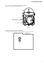
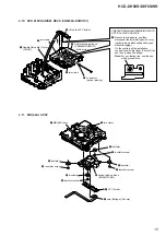
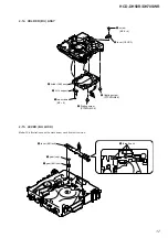
Be sure to bridge here, and then disconnect the
wire (flat type) (24 core).
(optical pick-up block will be destroyed without bridging.)
On the contrary at the installation, connect the
wire (flat type) (24 core) first, and then remove the bridge.
Note: For a soldering iron, use the one with a ground wire.
PRECAUTION WHEN REMOVING OPTICAL PICK-UP
BLOCK
Содержание HCD-DH50R
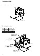
Страница 9: ...HCD DH50R DH70SWR 9 ARRANGEMENT OF LEAD WIRE lead wire lead wire ...
Страница 87: ...MEMO HCD DH50R DH70SWR 87 ...


