72
HCD-AZ2D/AZ5D
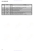
MAIN BOARD IC401 M30622MEP-A06FPU0 (SYSTEM CONTROLLER)
Pin No.
Pin Name
I/O
Description
1
P_SM_DATA
O
Serial data output to the stream processor
2
P_SM_CLK
O
Serial data transfer clock signal output to the stream processor
3
ML9208 RESET
O
Reset signal output to the fluorescent indicator tube driver “L”: reset
4
SIRCS
I
Remote control signal input from the remote control receiver
5
ML9208 DATA
O
Serial data output to the fluorescent indicator tube driver
6
ML9208 CS
O
Chip select signal output to the fluorescent indicator tube driver
7
ML9208 CLK
O
Serial data transfer clock signal output to the fluorescent indicator tube driver
8
BYTE
I
External data bus line byte selection signal input terminal Fixed at “L” in this set
9
CN VSS
–
Ground terminal
10
XC-IN
I
Sub system clock input terminal (32.768 kHz)
11
XC-OUT
O
Sub system clock output terminal (32.768 kHz)
12
RESET
I
System reset signal input terminal “L”: reset For several hundreds msec. after the
power supply rises, “L” is input, then it change to “H”
13
X-OUT
O
Main system clock output terminal (5 MHz)
14
VSS
–
Ground terminal
15
X-IN
I
Main system clock input terminal (5 MHz)
16
VCC
–
Power supply terminal (+3.3V)
17
NMI
I
Non-maskable interrupt input terminal Fixed at “H” in this set
18
USB_A_DET
I
USB memory detection signal input terminal Not used
19
P_DVD_I_
I
Disc slot in/out detection switch input terminal
MTK_SLOT_IN
20
AC-CUT
I
AC cut on/off detection signal input terminal “L”: AC cut on
21
TC A HALF
I
Deck-A cassette detection signal input from the tape mechanism deck block “L”:
cassette in
22
TC A PLAY SW
I
Deck-A playback detection signal input from the tape mechanism deck block “L”
playback
23
P_VIDEO_MUTE
O
Video muting on/off control signal output to the video amplifier “H”: muting on
24
BACKLIGHT
O
LED drive signal output for back light “H”: LED on
25
P_I_MREQ
I
Muting request signal input from the servo DSP
26
P_I_DVD_XIFCS
I
Chip select signal input from the servo DSP
27
P_I_KRMOD
I
Karaoke mode selection signal input from the servo DSP
Busy signal output to the servo DSP
IIC data transfer clock signal output terminal Not used
IIC data output terminal Not used
Serial data output to the servo DSP
I
Serial data input from the servo DSP
Serial data transfer clock signal output to the servo DSP
Reset signal output to the servo DSP “L”: reset
Deck-A side capstan/reel motor drive signal output terminal “L”: FWD/stop, “H”:
REV
36
TC A TRG
O
Deck-A side trigger plunger drive signal output terminal “H”: plunger on
37
TUNED
I
Tuning detection signal input from the tuner unit “L”: tuned
38
ST-DOUT
O
PLL serial data output to the tuner unit
39
ST-CLK
O
PLL serial data transfer clock signal output to the tuner unit
40
ST-DIN
I
PLL serial data input from the tuner unit
41
ST-CE
O
PLL serial chip enable signal output to the tuner unit
42
P_LINK_LFE_SW
O
Audio signal (for sub woofer) selection signal output terminal (HCD-AZ5D only)
43
NO USE
O
Not used
44
P_TC_AMS_MUTE
O
Automatic music sensor muting on/off control signal output terminal “L”: muting on
www. xiaoyu163. com
QQ 376315150
9
9
2
8
9
4
2
9
8
TEL 13942296513
9
9
2
8
9
4
2
9
8
0
5
1
5
1
3
6
7
3
Q
Q
TEL 13942296513 QQ 376315150 892498299
TEL 13942296513 QQ 376315150 892498299


