


1-2
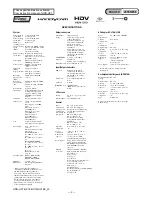
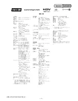
HDR-HC1/HC1E/HC1K/HC1EK_L2
ENGLISH
JAPANESE
ENGLISH
JAPANESE
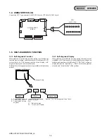
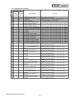
1-5. SELF-DIAGNOSIS FUNCTION
1-5-1. Self-diagnosis Function
When problems occur while the unit is operating, the self-diagnosis
function starts working, and displays on the viewfinder or LCD
screen what to do. This function consists of two display; self-
diagnosis display and service mode display.
Details of the self-diagnosis functions are provided in the Instruction
manual.
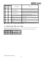
1-5-2. Self-diagnosis Display
When problems occur while the unit is operating, the counter of the
viewfinder or LCD screen shows a 4-digit display consisting of an
alphabet and numbers, which blinks at 3.2 Hz. This 5-character
display indicates the “repaired by:”, “block” in which the problem
occurred, and “detailed code” of the problem.
1 1
3 1
C
Repaired by:
Refer to “1-5-3. Self-diagnosis Code Table”.
Indicates the appropriate
step to be taken.
E.g.
31 ....Reload the tape.
32 ....Turn on power again.
Block
Detailed Code
Blinks at 3.2Hz
C : Corrected by customer
H : Corrected by dealer
E : Corrected by service
engineer
Viewfinder or LCD screen
C : 3 1 : 1 1
1
1
16
16
8
9
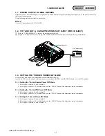
CN7005
NN-001 BOARD
(SIDE A)
CPC-7
(J-6082-382-A)
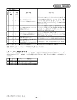
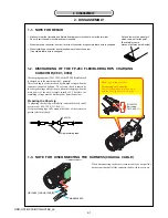
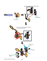
1-4. USING SERVICE JIG
Connect the CPC-7 jig connector (J-6082-382-A) to the CN7005 of NN-001 board.


