


1-7
FWD-50PX1
PSW
3
x
6
PSW
3
x
6
PSW
3
x
6
M8
x
16
Connectors
Clamper
Clampers
Clampers
QB block
assembly
Connector
Connector
Side frame
Board cover
assembly
PSW
3
x
6
Option case bracket
assembly
Flexible flat cable
Harness
Connectors
Conductive
cushion
Scan B board
Scan A board
Board holders
Board
holders
Y drive board
Screw
[A]
Screw
[B]
Screw
[C]
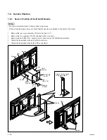
1-3-5. Y Drive Board
1.
Remove the rear cover assembly.
(Refer to Section 1-2-1.)
2.
Remove the five connectors.
3.
Remove the harness from the eight clampers.
4.
Remove the bolt (M8
x
16) and four screws (PSW3
x
6), then remove the QB block assembly in the
direction shown by the arrow.
5.
Remove the three screws (PSW3
x
6), then remove
the side frame and board cover assembly.
6.
Remove the four screws, then remove the option case
bracket assembly.
7.
Disconnect the harness and flexible flat cable from the
connectors on the Y drive board.
8.
Remove the two connectors from the scan A board and
scan B board.
9.
Remove the two screws [B], six screws [A], five
screws [C] and four board holders, then remove the Y
drive board.
10. Install the Y drive board in the reverse order of steps 1
to 9.
Содержание FWD-50PX1 (English: pgs. 52-97)
Страница 48: ......
Страница 80: ......
Страница 103: ...9 1 FWD 50PX1 9 1 Section 9 Board Layouts Index Board Name Page B 9 2 H1 9 6 H2 9 6 Q 9 4 SP 9 6 S 9 6 U1 FWD 50PX1 9 7 ...
Страница 105: ...9 3 FWD 50PX1 9 3 B B B B SIDE SUFFIX 11 A 1 2 3 B C D E F G H ...
Страница 107: ...9 5 FWD 50PX1 9 5 Q Q A 1 2 3 4 B C D E F G H Q B SIDE SUFFIX 11 ...
Страница 109: ...9 7 FWD 50PX1 9 7 U1 FWD 50PX1 U1 FWD 50PX1 U1 A SIDE SUFFIX 11 FWD 50PX1 U1 B SIDE SUFFIX 11 FWD 50PX1 ...
Страница 110: ......
Страница 112: ...Printed in Japan Sony Corporation 2004 10 22 B P Company 2004 FWD 50PX1 SY FWD 50PX1N SY E 9 968 064 01 ...


