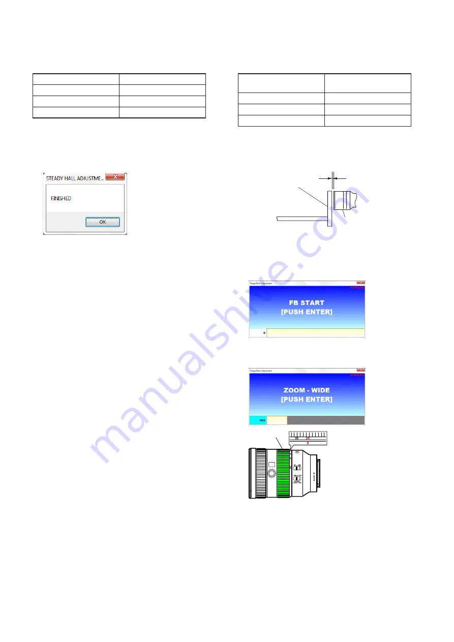
Sony FE 24-105mm F4 G OSS Скачать руководство пользователя страница 68

5-28

SEL24105G

(5) Flange Back (S)

•  Adjust the flange back of inner focus lens.

Subject

Flange back adjustment jig 
+ FB adjustment chart

Operation on Lens side

•  Zooming ring

Type of the camera

ILCE-5000

Shooting Mode of the camera P mode (Program Auto)

Preparation

Attach the FB adjustment chart to the flange back adjustment jig, and 
set the flange back adjustment jig as shown in the following figure.

Flange back
adjustment jig

Within 10 mm

Lens to be tested

Zoom: TELE end

Adjusting Method

1.  Click the [Flange Back (S)] button in the Adjustment and Inspec-

tion.

2.  The START screen is displayed, after the preparation of adjust-

ment is completed, press the ENTER key.


3.  “ZOOM - WIDE” is displayed, set the zooming ring to the WIDE 

end (focal length: 24 mm).


Zooming ring

4.  When the ENTER key is pressed, automatic adjustment of WIDE 

end is started.

– Continued on next page –

(4) Steady Hall (S)

•  Adjust the position detection hall element for shake compensation.

Subject

Not required

Operation on Lens side

Not required

Type of the camera

ILCE-5000

Shooting Mode of the camera P mode (Program Auto)

Adjusting Method

1.  Click the [Steady Hall (S)] button in the Adjustment and Inspec-

tion, the adjustment will start.

2.  “FINISHED” is displayed when the adjustment is completed, 

then click the [OK] button.


Содержание FE 24-105mm F4 G OSS

Страница 1: ...the equivalent focal length in 35mm format when mounted on an Interchangeable Lens Digital Camera equipped with an APS C sized image sensor 2 Angle of view 1 is the value for 35mm cameras and angle of view 2 is the value for Interchangeable Lens Digital Cameras equipped with an APS C sized image sensor 3 Minimum focus is the distance from the image sensor to the subject The minimum focus is 0 41 m...

Страница 2: ...ldering iron tips used for unleaded solder and those for leaded solder so they are managed separately Mixing unleaded solder and leaded solder will cause detach ment phenomenon 注意 如果电池更换不当会有爆炸危险 只能用同样类型或等效类型的电池来更换 务必按照说明处置用完的电池 1 4 SAFETY CHECK OUT After correcting the original service problem perform the following safety checks before releasing the set to the customer 1 Check the area of your rep...

Страница 3: ... adjustment data in the following procedure Before main board replacement Command of E Mount LensAdjustment AdjustmentApplica tion for Service is set to READ to implement the Adjustment Data Backup After main board replacement Command of E Mount Lens Adjustment Adjustment Appli cation for Service is set to WRITE SAVE to implement the Adjustment Data Backup ...

Страница 4: ...A do not open it with excessive force When closing the connector s holder press it evenly while pushing a flexible board in direction B A A Holder Connector Flexible Board B Holder Connector Flexible Board Make sure that the flat cable and flexible board are not cracked or bent at the contact end Do not apply excessive force to the gilded flexible board Cut and remove the part of gilt which comes ...

Страница 5: ...0_4 5_4 0 cam follower G_B 5 0_4 5_4 0 cam barrel assy 2nd lens barrel assy mount assy mount block rear shading barrel cam follower G_A 5 0_4 5 cam follower G_A 5 0_4 5 cam follower G_A 5 0_4 5 filter screw barrel 1st group assy back adjustment washer 1st moving frame assy cam shading barrel cam pin shaft M cam pin shaft M cam pin shaft M back adjustment washer conductive tape adjustment shim boar...

Страница 6: ... BOARD BLOCK Page 2 7 2 2 8 REAR BARREL BLOCK Page 2 7 2 2 9 APPEARANCE ASSY Page 2 8 2 2 10 ZOOM RING ASSY Page 2 9 2 2 12 FOCUS RING Page 2 10 2 2 11 FOCUS RING RUBBER Page 2 10 2 2 13 OUTER BLOCK ASSY Page 2 11 2 2 14 ZMR ASSY Page 2 12 2 2 15 1ST MOVING FRAME ASSY Page 2 13 2 2 16 3 5TH GROUP BLOCK Page 2 14 2 2 17 2ND LENS BARREL ASSY Page 2 15 OPTICAL AXIS ADJUSTMENT RESOLVING POWER CURVATUR...

Страница 7: ...the numerical order given 2 2 2 FRONT RING rear mount side front lens side 1 Rotate the front ring in the direction of the arrow and remove it 2 2 3 FILTER SCREW BARREL rear mount side front lens side 1 six tapping screws BTITE 1 4 u 5 2 filter screw barrel ...

Страница 8: ...side front lens side 1 three tapping screws TP1 7 u 5 2 1st group assy 3 three back adjustment washers Note Take note of the amount of back adjustment washers 2 2 5 ZOOM RING RUBBER rear mount side front lens side 2 guard tape Z 1 zoom ring rubber ...

Страница 9: ...sy Note 1 Take care not to damage the flexible board 7KH PRXQW DVV FDQ EH GLVDVVHPEOHG DV VKRZQ LQ WKH ILJXUH EHORZ mount assy from front lens side BL contact assy mount block rear shading barrel conductive tape tapping screw TP1 4 u 2 tapping screw TP1 4 u 2 tapping screw TP1 4 u 2 tapping screw TP1 4 u 2 5 four adjustment shims Note 2 Take note of the amount of adjustment shims ...

Страница 10: ...H ERDUG EORFN FDQ EH GLVDVVHPEOHG DV VKRZQ LQ WKH ILJXUH EHORZ rubber bush A rubber bush A rubber bush A rubber bush A two rubber bushs A two rubber bushs A 1 Lift up the CL 1058 board block after removing eight rubber bush A from eight places of bosses 2 2 8 REAR BARREL BLOCK 2 rear barrel block Note Take care not to damage the flexible board rear mount side front lens side rear barrel assy mount...

Страница 11: ...e 8 six screws M1 7 u 5 4 Pull out the ZMR flexible board from the connector 7 Insert the ZMR flexible board in the space of the ZMR assy 3 Peel off the MP cushion 5 Remove the flexible board 6 Peel off the LF 2212 flexible board 0 Draw the flexible board out of the hole 0 Draw the flexible board out of the hole 9 Lift up the appearance assy Note Take care not to damage the flexible board qa appea...

Страница 12: ...M RING ASSY rear mount side front lens side 1 Rotate the zoom ring assy in the direction of the arrow align the hole of the zoom ring assy with the position shown in the figure 2 zoom ring assy 3 ESD gasket groove hole slider ...

Страница 13: ...rd tape F 1 focus ring rubber 2 2 12 FOCUS RING 4 focus ring rear mount side front lens side 1 Rotate the focus ring and align the hole of the focus ring with the focus ring key 2 screw B1 4 u 3 2 screw B1 4 u 3 2 screw B1 4 u 3 3 focus ring key 3 focus ring key 3 focus ring key ...

Страница 14: ... ASSY rear mount side front lens side 5 outer block assy outer barrel assy 3 tapping screw P1 4 u 2 5 3 tapping screw P1 4 u 2 5 3 tapping screw P1 4 u 2 5 4 three claws 2 ESD gasket 1 SP cushion 1 SP cushion 1 SP cushion 1 SP cushion ...

Страница 15: ...2 12 SEL24105G 2 2 14 ZMR ASSY 2 ZMR assy 1 two screws M1 7 u 3 5 rear mount side front lens side ...

Страница 16: ...05G 2 2 15 1ST MOVING FRAME ASSY rear mount side front lens side 2 1st moving frame assy 1 cam pin A 1 cam pin A 1 cam pin A 4 three cam followers G_A 5 0_4 5 3 cam pin shaft M 3 cam pin shaft M 3 cam pin shaft M ...

Страница 17: ... front lens side 5 3 5th group block 4 three cam followers G_B 5 0_4 5_4 0 3 cam pin G_B 3 cam pin G_B 3 cam pin G_B 2 main FPC plate 1 two screws M1 7 u 2 5 torasuta CH G17 mask block assy main FPC plate 3 5th group assy 7KH WK JURXS EORFN FDQ EH GLVDVVHPEOHG DV VKRZQ LQ WKH ILJXUH EHORZ ...

Страница 18: ...RREL ASSY rear mount side front lens side 5 2nd lens barrel assy 4 three cam followers G_B 5 0_4 5_4 0 3 cam pin G_B 3 cam pin G_B 3 cam pin G_B 2 Remove by rotating the cam shading barrel in the direction of the arrow 1 adhesive bond ...

Страница 19: ...REL ASSY Page 2 27 2 3 11 APPEARANCE ASSY Page 2 25 2 3 6 OUTER BLOCK ASSY Page 2 21 2 3 7 FOCUS RING Page 2 22 2 3 8 FOCUS RING KEY Page 2 23 2 3 9 FOCUS RING RUBBER Page 2 23 2 3 12 ZOOM LINKAGE PIN Page 2 26 2 3 19 ZOOM RING RUBBER Page 2 30 2 3 10 ZOOM RING ASSY Page 2 24 2 3 5 ZMR ASSY Page 2 20 2 3 4 1ST MOVING FRAME ASSY Page 2 19 2 3 3 3 5TH GROUP BLOCK Page 2 18 2 3 2 2ND LENS BARREL ASSY...

Страница 20: ...th ditch and install the 2nd lens barrel assy marking 4 three cam followers G_B 5 0_4 5_4 0 Note When replacing the cam follower G_B 5 0_4 5_4 0 choose parts that do not cause backlash and confirm that movement is smooth 1 Rotate the zoom cam barrel in the direction of the arrow cam barrel assy 5 cam pin G_B 5 cam pin G_B 5 cam pin G_B ditch 6 Install by rotating the cam shading barrel in the dire...

Страница 21: ... the cam follower G_B 5 0_4 5_4 0 choose parts that do not cause backlash and confirm that movement is smooth 8 cam pin G_B 8 cam pin G_B 8 cam pin G_B 9 main FPC plate 0 two screws M1 7 u 2 5 torasuta CH ditch marking 5 Align the position of ditches 4 Rotate the zoom cam barrel in the direction of the arrow 1 3 5th group assy 3 Insert the flexible board in the main FPC plate 2 Make valley fold on...

Страница 22: ...cam pin A 3 three cam followers G_A 5 0_4 5 Note 1 When replacing the cam follower G_A 5 0_4 5 choose parts that do not cause backlash and confirm that movement is smooth 4 cam pin shaft M 4 cam pin shaft M 4 cam pin shaft M 2 Align the position of ditches 1 Rotate the zoom cam barrel in the direction of the arrow Note 2 Install the cam pin shaft M as shown in the direction of figure marking ditch...

Страница 23: ...2 20 SEL24105G 2 3 5 ZMR ASSY 1 ZMR assy 2 two bosses 3 two screws M1 7 u 3 5 rear mount side front lens side ...

Страница 24: ... install the outer block assy outer barrel assy FH button guide line guide line switch 3 tapping screw P1 4 u 2 5 3 tapping screw P1 4 u 2 5 3 tapping screw P1 4 u 2 5 2 three claws 4 ESD gasket 5 SP cushion 5 SP cushion guide line 5 SP cushion 6 Apply grease 6 Apply grease 6 Apply grease guide line 5 SP cushion 6 Apply grease ...

Страница 25: ...nt side front lens side rear mount side front lens side 1 Apply grease total two position potentiometer 3 focus ring focus ring 2 Apply grease total four position Note Grease must not attach to this part Note Grease must not attach to this part Note Grease must not attach to this part ...

Страница 26: ... careful of the direction of installation out side inner side Note Be careful of the direction of installation 5 Apply grease total one position 4 Rotate the focus ring a little in the direction of the arrow focus ring key focus ring key 5 Apply grease total two position 2 3 9 FOCUS RING RUBBER rear mount side front lens side 1 guard tape F guard tape F 2 focus ring rubber 3DVWLQJ SRVLWLRQ RI WKH ...

Страница 27: ...ont lens side 4 Rotate the zoom ring assy in the direction of the arrow 3 Align the hole of the zoom ring assy with slider and install the zoom ring assy 1 ESD gasket groove hole slider 2 Match the slider with the position shown in the figure rib rib center ...

Страница 28: ... 4 six screws M1 7 u 5 Note 3 Apply the adhesive bond to the tip of screws 5 Paste the LF 2212 flexible board 7 Insert the ZMR flexible board to the connector of LF 2212 flexible board 6 Match the flexible board with the shape of the ditch and fit it 8 MP cushion pasting reference 1 Insert the ZMR flexible board in the space of the ZMR assy Note 2 When installing the appearance assy assy be carefu...

Страница 29: ... pin 2 zoom linkage pin 1 Rotate the zoom ring assy and align the hole of the zoom ring assy with the screw hole screw hole hole hole screw hole 2 3 13 G17 MASK BLOCK ASSY B 40 B 40 rear mount side front lens side 1 G17 mask block assy 2 three claws 3 two adhesive bonds 3 adhesive bond ...

Страница 30: ... mount side front lens side 4 boss 4 boss switching lever ditch rear barrel block from rear mount side 5 three tapping screws TP1 7 u 5 Note 1 Be careful of the direction of installation 3 Align two switching levers with two ditches and install the rear barrel block Note 2 Take care not to damage the flexible board ...

Страница 31: ...t side front lens side long rear mount side short front lens side rubber bush A 2 3 16 CL 1058 BOARD BLOCK rear mount side front lens side rubber bush A total eight pieces boss total eight places 3 Align rubber bush A total eight pieces and bosses total eight places and install the CL 1058 board block 1 flexible board Note Take care not to damage the flexible board 2 flexible board Note Take care ...

Страница 32: ...2 6 tapping screw TP1 4 u 2 8 Crease the BL contact flexible board Mountain fold Valley fold 2 3 18 MOUNT ASSY 4 four screws TP2 u 8 2 BL contact flexible board 3 mount assy rear mount side front lens side mount assy from rear mount side Note 2 Shim must not protrude of the rear barrel Note 3 Shim must not overlap with the BL contact flexible board and the conductive tape 1 Paste four adjustment s...

Страница 33: ...irection of installation Note 2 The edge of the guard tape Z does not come over the hole 2 3 20 1ST GROUP ASSY rear mount side front lens side 2 Temporarily fasten the three tapping screws TP1 7 u 5 4 Tighten the three tapping screws TP1 7 u 5 1 Align the cutout of the 1st group assy with marking A and install the 1st group assy marking A cutout 3 three back adjustment washers Note Install exactly...

Страница 34: ...crew barrel boss Note When installing the filter screw barrel be careful not to catch the gasket square rib filter screw barrel from front lens side 2 3 22 FRONT RING B 40 filter screw barrel from front lens side rear mount side front lens side 1 Apply the adhesive bond total six position 2 Rotate the front ring in the direction of the arrow to the depths and install it ...

Страница 35: ...ction Shown the front lens side Black arrow direction Shown the rear mount side Ref No Part No Description Ref No Part No Description 1 4 690 155 01 FRONT RING 9121 2 4 300 106 11 BTITE 1 4 CH L 5 0 mm 3 4 690 154 01 FILTER SCREW BARREL 9121 4 4 300 115 21 TAPPING 1 7 CH L 5 0 mm 5 A 2180 233 A 1ST GROUP ASSY 6 selection parts BACK ADJUSTMENT WASHER Note Note This part is for resolving power adjus...

Страница 36: ...5 21 TAPPING 1 7 CH L 5 0 mm 60 4 597 406 01 MOUNT RUBBER 9135 61 A 2195 272 A REAR BARREL ASSY SERVICE 62 A 2194 815 A MASK BLOCK ASSY G17 63 2 660 401 41 SCREW M1 7 NEW TRU STAR P2 L 5 0 mm 64 4 693 029 01 ZOOM LINKAGE PIN 9121 65 4 731 818 01 MP CUSHION 9121 Note This part is for resolving power adjustment Refer to 3 5 SE LECTION PARTS and adjust the thickness by following the results of the re...

Страница 37: ...NG ASSY 104 3 686 458 11 SCREW P1 4 TAPPING L 2 5 mm 105 A 2195 271 A OUTER BLOCK ASSY SERVICE 106 A 2180 237 A OUTER BARREL ASSY 107 4 724 491 01 SP CUSHION 108 4 441 121 11 ESD GASKET 109 4 690 149 01 FOCUS RING 9121 110 3 254 135 01 SCREW B1 4 L 3 0 mm 111 4 690 156 01 FOCUS RING KEY 112 4 693 031 01 GUARD TAPE F 9121 113 4 690 157 01 FOCUS RING RUBBER 9121 114 4 570 981 01 ESD GASKET 9139 101 ...

Страница 38: ...SHAFT M 158 selection parts CAM FOLLOWER G_A 5 0_4 5 Note 159 4 570 830 01 CAM PIN G_B 9137 160 selection parts CAM FOLLOWER G_B 5 0_4 5_4 0 Note 161 A 2180 219 A CAM BARREL ASSY 162 4 273 894 02 CAM PIN A 163 A 2180 232 A 1ST MOVING FRAME ASSY 164 4 690 163 01 CAM SHADING BARREL 9121 Note Selection of this part is required for each unit Perform an opera tion check of the relevant locations refer ...

Страница 39: ...0 4 698 024 51 Transparent 0 250 4 698 024 61 Matte Black 0 300 4 698 024 71 Milky White Ref No 158 CAM FOLLOWER G_A 5 0_4 5 Perform an operation check of the relevant locations and select an appropriate part D2 D1 D1 mm D2 mm Part No Color 4 99 4 49 4 570 827 01 White 4 99 4 50 4 570 827 11 White 4 99 4 51 4 570 827 21 White 5 00 4 49 4 570 827 31 Black 5 00 4 50 4 570 827 41 Black 5 00 4 51 4 57...

Страница 40: ... MANUAL INSTRUCTION JAPANESE ENGLISH FRENCH SPANISH SIMPLIFIEDCHINESE 4 695 033 11 MANUAL INSTRUCTION GERMAN DUTCH SWEDISH ITALIAN PORTUGUESE ExceptChinese 4 695 033 21 MANUAL INSTRUCTION UKRAINIAN RUSSIAN TRADITIONALCHINESE KOREAN ARABIC ExceptChinese 501 X 2592 340 1 CAP S DIA 77 YM AFRONT Frontlenscap 502 4 159 701 03 REARLENSCAP 503 4 693 463 01 HOOD 9121 Lenshood 504 4 535 011 01 CASECL K2 Le...

Страница 41: ...tem Cam Barrel Assy 3 5th Group Assy 2nd Lens Barrel Assy 1st Moving Frame Assy 1st Group Assy ZMR Assy Outer Barrel Assy Zoom Ring Assy Focus Ring 9121 Mount Assy CL 1058 Board Complete Service Outer Block Assy Service Rear Barrel Assy Service Optical Axis Check Adjustment z Resolving Power Check Adjustment z z z z z z z z z z z z z E Mount Lens Adjustment Lens Device S z z z Lens Device2 S z z z...

Страница 42: ...ens Sleep END Perform the adjustment it does not improve the symptoms 5 2 2 Optical axis check Resolving power adj 5 3 Resolving power check Note 1 Perform the adjustment it does not improve the symptoms 5 2 3 Optical axis adjustment Note 1 Perform the Resolving Power Check by either 5 3 2 Projective Resolving Power Check or 5 3 3 Photographic Resolving Power Check Note 2 When it does not improve ...

Страница 43: ...ns Test Projector F J 6082 835 A 3 For Lens Test Projector Chart E mount attachment J 6082 775 A 4 For Lens Test Projector Screen Tape measure Sold on the market Plane mirror For SLRs 40 inch LCD monitor Full HD Camera ILCE 5000 ILCE 6300 for Focus Shift Adjustment General E mount Interchangeable Lens Digital Camera with Full Frame Sensor for Photographic Resolving Power Check Tripod For partial a...

Страница 44: ... For Flange Back Adjustment 1000 mm Collimator J 6082 604 A 8 110V J 6082 604 B 8 240V Flange back tester J 6082 606 A 9 FB tester stand J 6082 808 A 10 Camera table 200 200 J 6082 809 A 11 A mount attachment J 6082 607 A 12 A E mount attachment J 6082 798 A 13 Combination of theA E mount conversion attachment and the E Mount Extension Jig A E mount conversion attachment J 6082 845 A 14 E Mount Ex...

Страница 45: ...m Camera Table 200 200 FB Tester Stand Scale ring Eyepiece lens 7x Eyepiece ring 2 Looking through the eyepiece lens turn the eyepiece ring of the flange back tester so that cross line or scale in the view is the sharpest 3 Attach the flange back gauge 43 50 mm securely to theA mount attachment and hold them together 4 While applying light to the flange back gauge turn the focus ing knob of the fl...

Страница 46: ...uter See Note 1 B L Control Box Supplied with D sub 15 pin cable AC cable Sold on the market RS 232C Cable D sub 9 pin Male with securing screws D sub 9 pin Female with securing screws Straight type Sold on the market USB to serial cable D sub 9 pin Male Sold on the market Lens adjustment program BLG TestProgramV exe See Note 2 Note 1 Personal computer must have the condition that Windows 7 runs n...

Страница 47: ...wer button is made active When the password input window opens ask service head quarters about password In this case the ID shown in COM USER Characteristic Number must be informed YdDGAAHTJ in the example above Since this ID number is unique to the B L Control Box and personal computer if used another B L Control Box or per sonal computer another password is necessary 5 Connection to the lens mou...

Страница 48: ...the lens to be tested At this time confirm that both of the two LEDs on the B L Control Box are light If either or none of them does not light there is a problem LEDs for power supply check B L Control Box Power switch Note 1 Before detaching the lens after power is supplied be sure to click Power again and confirm that the two LEDs go out 9 Select Center Hold from the steady shot selection menu a...

Страница 49: ...ed If the reflected light position is deviated re adjust the lens projector position 11 Select Open from the iris selection menu and click Iris Iris setting Open 12 Rotate the zoom ring of the lens to be tested set the zoom position Note 2 This lens is not power zoom do not use the following zoom operation Zoom operation 13 Select from the focus selection menu Focus setting ...

Страница 50: ...in Fig f is in focus and then read the dial gauge value D 6 Calculate the CB value absolute difference between C and D and check that it is within the specification CB value C D 5 4 Fig d Fig e Fig f CB Specification Reference AS Astigmatism 0 09 mm or less CB Center Blur 0 13 mm or less 3 If the specifications of AS and CB are not satisfied perform the 5 2 3 Optical Axis Adjustment 5 2 3 Optical ...

Страница 51: ...Aperture Open 2 Attach the lens to be tested to the Lens Test Projector and set the equipment as shown in the figure below 3 Set the zoom to the arbitrary position 4 Turn ON the main switch of the Lens Test Projector 5 Turn ON the lamp switch of the Lens Test Projector 6 To set the lens surface and the screen in parallel align the plane mirror with the center projected image on the screen and adju...

Страница 52: ... tested FF APSC to the Lens Test Projector 1 Setting of Lens Test Projector Setting Procedure 1 Connect the B L Control Box with the personal computer and the Lens Test Projector 2 Attach the lens to be tested to the Lens Test Projector and set the equipment as shown in the figure below 3 Turn ON the main switch of the Lens Test Projector 4 Turn ON the lamp switch of the Lens Test Projector 5 To s...

Страница 53: ...bout password In this case the ID shown in COM USER Characteristic Number must be informed YdDGAAHTJ in the example above Since this ID number is unique to the B L Control Box and personal computer if used another B L Control Box or per sonal computer another password is necessary 5 Connection to the lens mount block is established and the Power button is made active Procedure of Finishing 1 Click...

Страница 54: ...o supply power to the lens to be tested At this time confirm that both of the two LEDs on the B L Control Box are light If either or none of them does not light there is a problem LEDs for power supply check B L Control Box Power switch Note 1 Before detaching the lens after power is supplied be sure to click Power again and confirm that the two LEDs go out 4 Select Center Hold from the steady sho...

Страница 55: ...iated re adjust the lens projector position 6 Select Open from the iris selection menu and click Iris Iris setting Open 7 Rotate the zooming ring of the lens to be tested and set the focal length to the arbitrary position Note 2 This lens is not power zoom do not use the following zoom operation Zoom operation 8 Select JOG from the focus menu Not used this section Check off Use this section Contin...

Страница 56: ...peration window Select focus step value Select and enter focus step speed Focus drive near Focus drive far Focus position indicator 10 Adjust the focus position with Near and Far while selecting Focus Step and Low Mid High and then click OK to close the focus JOG window ...

Страница 57: ... lines More than 20 lines 35 1 4 50 2 0 70 2 8 105 4 2 Checking Procedure 1 Set the projection distance of the lens projector Refer to Reference value 2 Set the focus 3 Bring the projector into focus so that fine lines of the center projected image y 0 on the screen can be clearly seen as much as possible by operating the program screen Saggital S Meridional M The number of projective resolving po...

Страница 58: ...re fine lines beyond resolving power are visible as black and white stripes as if resolution is made In this case black and white of three stripes are reversed and seen as if they are two or four lines in some cases Be careful not to confuse this phenomenon with the resolution limit Correct resolution Spurious resolution 6 Change the focal length and projection distance of the lens to be tested an...

Страница 59: ...e whole screen Furthermore move it to the 100 mm rear from that position 0 8 0 6 0 5 0 3 0 3 0 5 0 6 0 8 2 Checking Method Checking Procedure 1 Set to manual focus on status that the 1 Setting of Equipment condition 2 Focus and shoot with self timer 3 Keep focusing as step 2 change the object distance to the shooting distance position 100 mm of step 1 then shoot two times with self timer 4 Check t...

Страница 60: ...ment washer to adjust the partial blur Partial blur Set the zoom to the TELE end Change the thick ness of the side where blurring occurs Front focus Make the washer thicker Rear focus Make the washer thinner back adjustment washer back adjustment washer back adjustment washer 3 Tighten the three screws loosened at step 1 4 Perform the check and adjustment repeatedly until the partial blur is resol...

Страница 61: ... thicker Rear focus Make the washer thinner adjustment shim 2 Perform the check and adjustment repeatedly until the partial blur curvature is resolved Note If the partial blur curvature cannot be resolved even after the adjustment replace the mount assy ADJUSTMENT SHIM Thickness mm Part No Color 0 050 4 698 024 01 Red 0 075 4 698 024 11 Glossy Black 0 100 4 698 024 21 Glossy Silver 0 125 4 698 024...

Страница 62: ...e back adjustment jig Zoom TELE end Lens to be tested Siemens star chart Image sensor position mark Siemens star chart When the subject is a siemens star chart 510 mm Camera Tripod Lens to be tested AC adaptor AC To tripod screw Personal computer USB cable HASP key To USB connector To USB connector 1 Installation For adjustment of the SEL24105G prepare a version 1 4 3 0 or higher of the lens adjus...

Страница 63: ...installer start up screen appears then click the Next button to start the installation 6 The following screen appears when the installation is complete then click the Close button 7 Create a shortcut icon of the E Mount LensAdjustment Adjust ment Application for Service on the desk top 8 Create a folder of C FSA VX9121 in C drive and store the following two files FnoFocusShift_VX9121_20170616_02 x...

Страница 64: ...justment Procedure of Finishing 1 Click the Disconnect button and check that the connection status becomes Disconnect 2 Click the button on the upper right of the main window to finish the E Mount Lens Adjustment 3 Turn off the power of camera 4 Disconnect the AC adaptor 5 5 4 Adjustment Method of Each Item 1 Lens Device S Adjust and inspection the focusing ring Subject Not required Operation on L...

Страница 65: ...ocus and zoom Adjust the frequency of focus PWM Perform thermistor inspection Subject Not required Operation on Lens side Zooming ring Type of the camera ILCE 5000 Shooting Mode of the camera P mode Program Auto Adjusting Method 1 Click the Lens Device2 S button in the Adjustment and In spection 2 The START screen is displayed after the preparation of adjust ment is completed press the ENTER key 3...

Страница 66: ...leted message screen is dis played in the following Set the zooming ring to the WIDE end focal length 24 mm Zooming ring 9 When the ENTER key is pressed message screen is displayed in the following Set the zooming ring to the TELE end focal length 105 mm Zooming ring 10 When the ENTER key is pressed automatically starts the each adjustments and inspections 11 LENS DEVICE 2 CHECK OK is displayed pr...

Страница 67: ...n 2 Push the FH Button is displayed operate the focus hold button accordance with the message Focus hold button 3 The message screen is displayed in the following order Operate the focus mode switch accordance with the message Focus mode switch 4 The message screen is displayed in the following order Operate the shake compensation switch accordance with the message Shake compensation switch 5 SW C...

Страница 68: ...stment and Inspec tion 2 The START screen is displayed after the preparation of adjust ment is completed press the ENTER key 3 ZOOM WIDE is displayed set the zooming ring to the WIDE end focal length 24 mm Zooming ring 4 When the ENTER key is pressed automatic adjustment of WIDE end is started Continued on next page 4 Steady Hall S Adjust the position detection hall element for shake compensation ...

Страница 69: ...n small increments to the TELE WIDE side for fine adjustment an error may occur Rotate to only one direction TELE side and adjust the position If it deviates from the specified position return to WIDE side greatly and try again The bar and value hexadecimal numeral under the window are displayed by interlocking with the behavior of the zooming ring A green line is displayed on the bar under the wi...

Страница 70: ...ording the adjustment data and releasing from adjustment mode are performed automatically and FINISHED is displayed when the process is completed then click the OK button 6 F Number S Perform focus actuator inspection Perform actuator damage inspection Adjust the F number Subject Not required Operation on Lens side Zooming ring Type of the camera ILCE 5000 Shooting Mode of the camera P mode Progra...

Страница 71: ...Image sensor position mark Siemens star chart 510 mm Adjusting Method 1 Click the FSA1 S button in the Adjustment and Inspection 2 The START screen is displayed after the preparation of adjust ment is completed press the ENTER key 3 Set FocusSW AF is displayed set the focus mode switch to the AF Focus mode switch 4 When the ENTER key is pressed message screen is displayed in the following Set the ...

Страница 72: ...the subject 12 When the ENTER key is pressed automatic adjustment is started 13 After the automatic adjustment is completed message screen is displayed in the following Set the siemens star chart on the subject 14 When the ENTER key is pressed automatic adjustment is started 15 After the automatic adjustment is completed message screen is displayed in the following Set the zooming ring to the TELE...

Страница 73: ...d set the shake compensation switch to the ON Shake compensation switch 4 Lens Sleep OK is displayed press the ENTER key 5 Check that the LENS SLEEPOK is displayed on the Message History window 20 After the automatic adjustment is completed the calculation processing of the quantity of correction is started The display of the message screen changes as follows Processing time 10 to 15 minutes 21 FS...

Страница 74: ...Revision History SEL24105G Ver Date History Contents 1 0 2017 10 Official Release ...

Отзывы: