
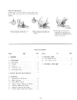

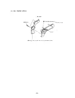


REMOVALOFANODECAP
Ground using the slotted screwdriver properly when remov-
ing the anode cap to prevent any electrical shocks from
@Turn up one side of the rubber cap in the
direction indicated by the arrow
@Using a thumb pull up the rubber cap
firmly in the direction indicated by the
arrow
Anode
@When one
of the rubber cap is
separated from the anode button, the
anode-cap can be removed by turning
up the rubber cap and pulling up it in the
direction of the arrow
TABLEOFCONTENTS
Section
Section
Title
. . . . . . . . . . . . . . . . . . .
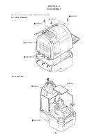
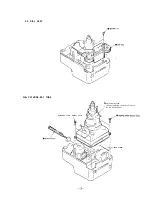
2. DISASSEMBLY
2-1.
Rear Cabinet . . . . . . . . . . . . . . . . . . . . . . . .
2-2.
D Board
. . . . . . . . . . . . . . . . . . . . . . . . . . . .
2-3.
Dial Assy . . . . . . . . . . . . . . . . . . . . . . . . . . . .
2-4.
Cathode-ray Tube . . . . . . . . . . . . . . . . . . . .
2-5.
Dial Pointer Setting . . . . . . . . . . . . . . . . . .
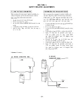
3. SAFETY RELATED ADJUSTMENTS . . . . . . . . . . . . 9
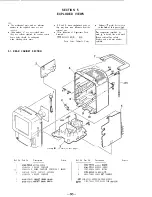
5. EXPLODED VIEWS
5-1.
Rear Cabinet Section . . . . . . . . . . . . . . . . . . .
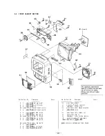
5-2.
Front Cabinet Section
. . . . . . . . . . . . . . . . . . . .
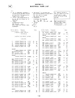
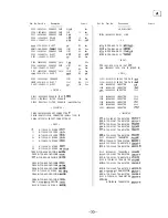
6 .
ELECTRICAL PARTS
. . . . . . . . . . . . . . .
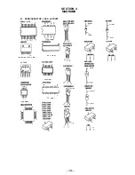
4. DIAGRAMS
4-1.
Semiconductor Lead Layouts . . . . . . . . .
4-2.
D i a g r a m . . . . . . . . . . . . . . . . . . . . . . . . .
4-3. Circuit Boards Location
. . . . . . . . . . . . . . .
4-4.
Printed Wiring Boards-A/R Boards-
4-5.
Schematic Diagram-A/R Boards- . . . . .
4-6.
Schematic Diagram-C/D/F Boards- . . .
4-7.
Printed Wiring Boards-C/D/F Boards-
10
. . . . . . . . 11
. . . . . . . . 14
. . . . . . . . 14
. . . . . . . . 17
. . . . . . . . 21
. . . . . . . . 25
30
31
32


