— 17 —
KV-13FM12/13FM13/13FM14/14FM12/14FM12A/14FM12C/14FM14
R G B B G R
R G B
R
R
R
G
B
G
B
G
B
R G B
B G R
R
G
B
R
G
B
B G R R G B
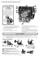
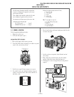
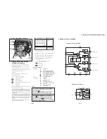
4. Tighten the deflection yoke screw.
5. Install the deflection yoke spacers.
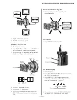
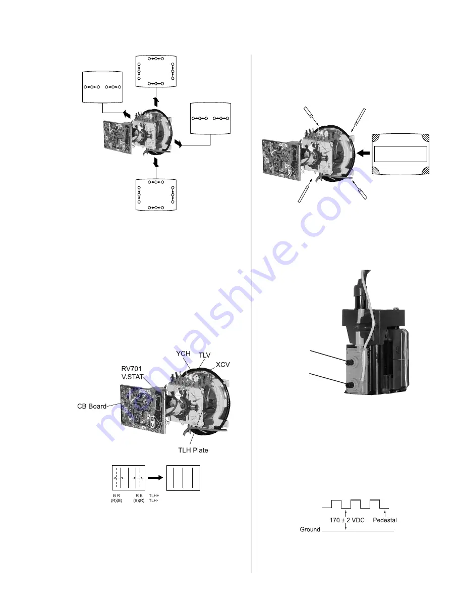
TLH Plate Adjustment
1. Input crosshatch pattern.
2. Adjust PICTURE QUALITY to standard, PICTURE and
BRIGHTNESS to 50%, and OTHER to standard.
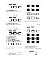
3. Adjust the Horizontal Convergence of red and blue dots
by tilting the TLH plate on the deflection yoke.
4. Adjust XCV core to balance X axis.
5. Adjust YCH VR to balance Y axis.
6. Adjust vertical red and blue convergence with V.TILT
(TLV VR). Perform adjustments while tracking items
1 and 2.
b
a
c
d
a
b
d
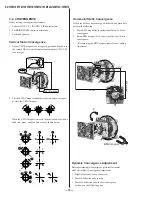
a-d: screen-corner
misconvergence
c
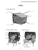
3-3. FOCUS
1. Adjust FOCUS control for best picture.
Focus (FV)
Screen (G2)
3-4. SCREEN (G2)
1. Input a dots pattern.
2. Set the PICTURE and BRIGHTNESS controls at minimum
and COLOR control at normal.
3. Adjust SBRT, GCUT, BCUT in service mode with an
oscilloscope as shown below so that voltages on the red,
green, and blue cathodes are 170± 2 VDC.
4. Observe the screen and adjust SCREEN (G2) VR in FBT
to obtain the faintly visible background of dot signal.
Screen-Corner Convergence
1. Affix a permalloy assembly corresponding to the
misconverged areas.
Содержание FD TRINITRON WEGA KV-13FM12
Страница 26: ... 26 KV 13FM12 13FM13 13FM14 14FM12 14FM12A 14FM12C 14FM14 NOTES ...
Страница 36: ......
Страница 50: ... 65 KV 13FM12 13FM13 13FM14 14FM12 14FM12A 14FM12C 14FM14 NOTES ...
Страница 51: ... 66 KV 13FM12 13FM13 13FM14 14FM12 14FM12A 14FM12C 14FM14 NOTES ...
Страница 52: ... 67 KV 13FM12 13FM13 13FM14 14FM12 14FM12A 14FM12C 14FM14 ...

