


2-2
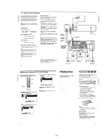
2-5. TRAY COVER REMOVAL
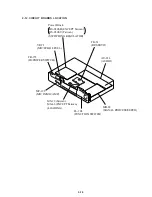
2-7. MECHANISM DECK REMOVAL
2-6. FRONT PANEL REMOVAL
2-8. TRAY REMOVAL
4
Tray cover
2
Pull the tray in the
direction of the
arrow
B
.
1
Insert a tapering driver into the aperture of the
unit bottom, and move the lever of chuck cam
in the direction of the arrow
A
.
3
Two claws
B
A
4
Screw
(B3)
2
Connector
(CN842)
3
Flat cable
(CN006)
1
Connector
(CN203)
5
Two screws
(B3)
9
Claw
8
Claw
!º
Front panel
6
Boss
7
Boss
2
Two flat cables
(CN003, 004)
3
Screw
(B3)
4
Mechanism deck
1
Connector
(CN001)
2
Chuck ass’y
4
Remove the tray in
the direction of the
arrow
B
.
3
Move the lever of chuck cam
in the direction of the arrow
A
.
1
Two screws
(BTP2.6
×
12)
B
A
Содержание DVP-K330
Страница 6: ...1 1 SECTION 1 GENERAL This section is extracted from in struction manual 3 866 505 11 DVP K330 ...
Страница 7: ...1 2 ...
Страница 8: ...1 3 ...
Страница 9: ...1 4 ...
Страница 10: ...1 5 ...
Страница 11: ...1 6 ...
Страница 12: ...1 7 ...
Страница 13: ...1 8 ...
Страница 14: ...1 9 ...
Страница 15: ...1 10 ...
Страница 16: ...1 11 ...
Страница 17: ...1 12 ...
Страница 18: ...1 13 ...
Страница 19: ...1 14 ...
Страница 20: ...1 15 1 15 E ...
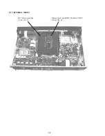
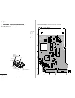
Страница 24: ...2 4 2 11 INTERNAL VIEWS DC motor loading 1 541 632 11 Optical pick up KHM 220AAA J1RP 8 820 081 03 ...
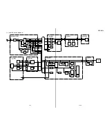
Страница 34: ...DVP K330 4 3 4 4 4 1 FRAME SCHEMATIC DIAGRAM FRAME 1 SCHEMATIC DIAGRAM FRAME 1 2 ...
Страница 35: ...DVP K330 4 5 4 6 FRAME 2 SCHEMATIC DIAGRAM FRAME 2 2 ...
Страница 63: ...DVP K330 4 59 4 60 VR 71 MIC ECHO LEVEL SCHEMATIC DIAGRAM Ref No VR 71 board 2 000 series MIC ECHO LEVEL VR 71 ...