background image

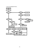
9-8

C.

E

Audio

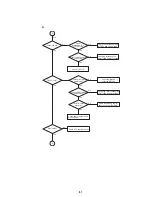
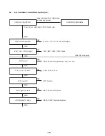
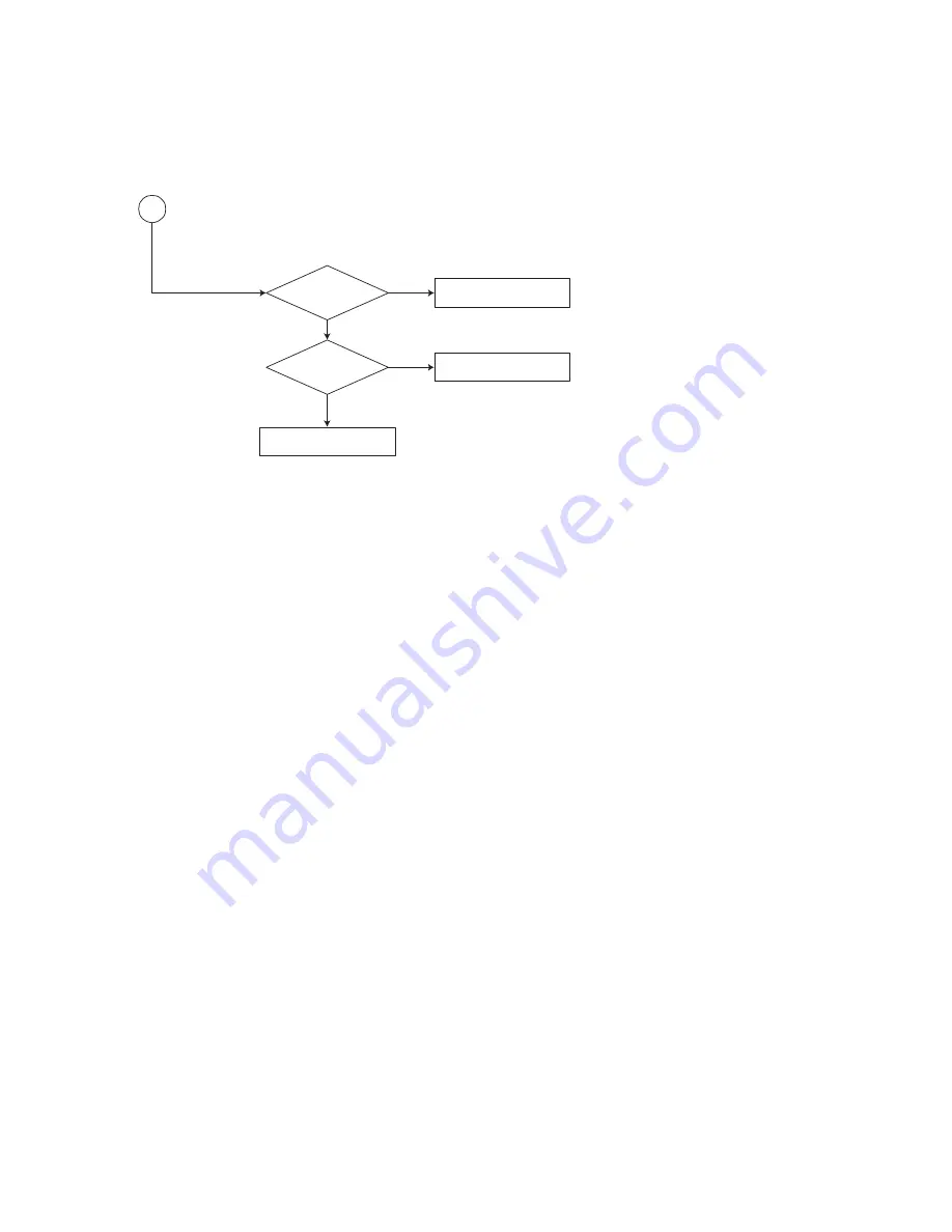
DAC received

correct data stream?

Normal

Audio DAC

out? (IC301)

Check Audio filter, amplify, mute
circuit. (IC301 Application circuit)?

Check connection between MT1389
& Audio DAC. (Check VRST, ACLK,
ABCK, ASDAT0)

Check the related circuit of
Audio DAC. (Check Audio
out Pin 14, 15,18,19)

Содержание DVP-FX705 - Portable Dvd Player

Страница 1: ...re than 95 dB Dynamic range audio More than 95 dB Harmonic distortion audio 0 008 Operating conditions Temperature 41 F to 95 F Operation status Horizontal Connectors Video output VIDEO Out 1 0 V p p 75 Ω negative sync ø3 5mm mini jack x 1 Audio output AUDIO Out analog audio 2 0 Vrms 1 KHz 0 dB ø3 5mm mini jack x 1 Earphone terminal ø3 5mm stereo mini jack x 2 Liquid Crystal Display Panel size 7 i...

Страница 2: ...particularly transis tors that were installed during a previous repair Point them out to the customer and recommend their replacement 4 Look for parts which though functioning show obvious signs of deterioration Point them out to the customer and recom mend their replacement 5 Check the line cord for cracks and abrasion Recommend the replacement of any such line cord to the customer 6 Check the B ...

Страница 3: ... 15 4 8 LCD Power 4 17 4 9 Battery Charge 4 19 4 10 Menu Key 4 21 4 11 TFT LCD Power 4 23 4 12 TFT LCD T100 4 25 5 PRINTED WIRING BOARDS 5 1 Circuit Boards Location 5 1 5 2 MAIN Board 5 3 5 3 KEY Board 5 7 5 4 TFT LCD Board 5 9 6 WAVEFORMS 6 1 Details and Waveforms on System Test and Debugging 6 1 6 2 Circut Voltage Chart 6 9 7 IC PIN FUNCTION DESCRIPTION 7 1 MPEG DSP RF Pin Function MAIN Board IC...

Страница 4: ... 4 MEMO ...

Страница 5: ...ent from that to which the receiver is connected Consult the dealer or an experienced radio TV technician for help Introductions 5 Precautions continued The power requirements and power consumption of this unit are indicated on the AC adaptor Check that the unit s operating voltage is identical with your local power supply On safety Caution The use of optical instruments with this product will inc...

Страница 6: ...been charged Leaving it connected may result in reduced battery performance Introductions 7 Precautions continued On handling the player Keep the lens on the player clean and do not touch it If you do so the lens may be damaged and the player will not operate properly Place the player in a location with adequate ventilation to prevent heat build up in the player Do not put any heavy object on top ...

Страница 7: ... monitor display where viewable by the driver Some states restrict the use of monitors and televisions in vehicles Where use is permitted the units should not be installed or operated so as to be viewable by the driver Precautions continued Introductions 9 Precautions continued On transportation When you transport this player use the original carton box and packing materials Before you move this p...

Страница 8: ...on for Standardization MPEG which compresses audio data Functions available for DVD VIDEOs and DVD RWs DVD Rs or DVD RWs DVD Rs in video mode Functions available for music CDs or CD Rs CD RWs in music CD format Functions available for DATA CDs CD ROMs CD Rs CD RWs containing MP3 audio tracks and JPEG image files JPEG MP3 Introductions 11 This Player Can Play the Following Discs continued MP3 MP3 i...

Страница 9: ...designed some playback features may not be available Also refer to the instructions supplied with the DVDs This product incorporates copyright protection technology that is protected by U S patents and other intellectual property rights Use of this copyright protection technology must be authorized by Macrovision and is intended for home and other limited viewing uses only unless otherwise authori...

Страница 10: ... 7 8 9 10 11 12 13 1 Power indicator page 23 POWER ON Green ON POWER OFF Green OFF 2 CHARGE indicator page 22 During recharging Orange ON 3 POWER and HOLD switch To turn off the power you need to press the POWER switch for at least one second This is to prevent the player from being accidentally turned off HOLD switch The hold function locks the buttons on the DVD player so that they will not work...

Страница 11: ...ing apparatus Doing so may cause a malfunction If you do not use the remote for an extended period of time remove the batteries to avoid possible damage from battery leakage and corrosion Remote Control 18 Identification of Controls continued AUDIO PREV NEXT CLEAR PLAY PAUSE STOP SET UP SCAN TOP MENU MENU DISPLAY RETURN SLOW REPEAT RANDOM A B PROGRAM ANGLE 1 2 3 6 5 4 7 8 0 9 DVD PORTABLE ENTER 1 ...

Страница 12: ... TOP MENU and MENU screen 20 RETURN button TOP MENU button Use the TOP MENU button to display the title screen included on DVD video discs To operate a menu screen follow the instructions in Using a Title Menu page 30 20 Power Connections AC Adaptor To DC IN 9 8V 1 2 3 AC power cord To AC outlet VOLUME PHONES PHONES AUDIO VIDEO AC adaptor supplied Follow steps 1 to 3 to connect When disconnecting ...

Страница 13: ...lete the indicator turns off 4 Disconnect the AC adaptor from the player and pull out the plug from the AC outlet after charging A Confirm the battery charge on the LCD screen during stop or playback When appears the charge indicator flashes in orange The battery mark does not appear during DVD or JPEG playback To check the battery charge stop playback If using the AC adaptor battery display does ...

Страница 14: ...k of the selected item begins For further information also refer to the jacket or case of the disc you are playing DVD 23 Basic Playback 1 2 3 4 LCD MODE COLOR BRIGHT VOLUME Down Up Basic Operation 24 Playing a Disc continued NOTES Place a disc with the playback side down on the spindle and push gently on the center of the disc so it goes into position Confirm LCD MODE position by pressing LCD MOD...

Страница 15: ...it select OFF to conserve power The LCD is turned off if you close the unit Horizontal lines may appear in the picture when the mode is switched to ZOOM but this is not an indication of a malfunction Playing a Disc continued 26 Stopping Play Press STOP during playback NOTE Do not touch the disc if it is still spinning when you open the lid Resume Play When play is stopped the unit records the poin...

Страница 16: ...peed 4 3 2 1 backward or 4 3 2 1 forward 3 To exit slow motion mode press PLAY DVD DVD DVD On Screen Display 28 You can display the general playback status on the screen Some items can be changed using the menu To use the on screen display 1 Press DISPLAY during playback 2 Press V v to select an item The selected item is highlighted 3 Press B b to change the setting You can also use the number but...

Страница 17: ...le options and chapters for the title Press B V v b and ENTER or press the numeric button s to select desired item Unless stated otherwise all operations described use the remote control Some features may also be available on the Setup menu Moving to another TITLE When a disc has more than one title you can move to another title Press DISPLAY while playback is stopped then the appropriate number 0...

Страница 18: ...b repeatedly until the desired Subtitle is selected Each time this button is pressed the LCD screen display changes Camera Angle If the disc contains scenes recorded at different camera angles you can change to a different camera angle during playback 1 Press ANGLE during playback 2 Press B b repeatedly until the desired Angle is selected NOTE You cannot change the angle during slow playback TIP T...

Страница 19: ...Press PAUSE during playback 2 To return to playback press PLAY ENTER or press PAUSE again Moving to another Track 1 Press PREV NEXT or briefly during playback to go to the next track or to return to the beginning of the current track 2 Press PREV twice briefly to go back to the previous track 3 You can play any track by inputting its number Search 1 Press SCAN SLOW m or M during playback The playe...

Страница 20: ...ad MP3 files and music from the Internet Our company has no right to grant such permission Permission should always be sought from the copyright owner Programmed Playback 36 The program function enables you to store the playback order of your favorite tracks from any disc in the player memory A program can contain 30 tracks 1 Insert a disc Audio CD or MP3 Discs AUDIO CD or AUDIO menu appears 2 Pre...

Страница 21: ...rase additional tracks on the list Erasing the Complete Program List 1 Press PROGRAM 2 Press b to move to the Program list 3 Use V v to select Clear All then press ENTER NOTE The programs are also cleared when the disc is removed 38 Random Play Random play Karaoke DVD CD MP3 You can playback titles or tracks in random order Random playback NOTE Random does not work with DVD movie discs 1 Press RAN...

Страница 22: ... cursor B or b once while viewing a picture to advance to the next or previous file To rotate picture Press V v while showing a picture to rotate the picture clockwise or counterclockwise To listen to MP3 music while watching a picture You can display files while listening to MP3 music files recorded on the same disc 1 Insert the disc containing the two types of files in the player 2 Press TOP MEN...

Страница 23: ... the Setup menu LANGUAGE SET UP Menu Language Select a language for the Setup menu and on screen display Disc Audio Subtitle Menu Select the language you prefer for the audio track disc audio subtitles and the disc menu Original Refers to the original language in which the disc was recorded Other To select another language press number buttons then ENTER to enter the corresponding 4 digit number a...

Страница 24: ...ore suitable scenes as an alternative The parental control feature allows you to block access to scenes below the rating you input thereby preventing your children from being able to view material you believe is unsuitable 1 Select Rating on the PARENTAL CONTROL menu then press b 2 To access the Rating Password and Country Code features you must input the 4 digit security code you created If you h...

Страница 25: ...nter the code of the country area whose standards were used to rate the DVD video disc based on the list in the reference chapter See Country Code List page 54 1 Select Country Code on the PARENTAL CONTROL menu then press b 2 Follow step 2 as shown left Rating 3 Select the first character using V v buttons 4 Press ENTER and select the second character using V v buttons 5 Press ENTER to confirm you...

Страница 26: ...he S VIDEO INPUT jack on the TV using the S Video cable Audio Connection to Your TV Connect the AUDIO OUT jack of the DVD Player to the AUDIO L and R INPUT jacks on the TV using the audio cables Do not connect the DVD Player s AUDIO OUT jack to the PHONES jack record deck of your audio system 47 VOLUME PHONES PHONES AUDIO VIDEO Rear of TV Right side of unit Audio Video cable Supplied Yellow S Vide...

Страница 27: ...vely grounded This car battery adaptor is for negatively grounded cars only Use the unit with the car engine running If you use the unit with the car engine stopped the car battery may become unusable This unit is not disconnected from the power source as long as it is connected to the cigarette lighter socket of a car Unplug the car battery cord from the cigarette lighter socket when not in use T...

Страница 28: ... 7378 Interlingua 7365 Irish 7165 Italian 7384 Japanese 7465 Javanese 7487 Kannada 7578 Kashmiri 7583 Kazakh 7575 Kirghiz 7589 Korean 7579 Kurdish 7585 Laothian 7679 Latin 7665 Latvian Lettish 7686 Language Code Lingala 7678 Lithuanian 7684 Macedonian 7775 Malagasy 7771 Malay 7783 Malayalam 7776 Maltese 7784 Maori 7773 Marathi 7782 Moldavian 7779 Mongolian 7778 Nauru 7865 Nepali 7869 Norwegian 787...

Страница 29: ...y HU India IN Indonesia ID Israel IL Italy IT Jamaica JM Japan JP Kenya KE Kuwait KW Libya LY Luxembourg LU Country Code Malaysia MY Maldives MV Mexico MX Monaco MC Mongolia MN Morocco MA Nepal NP Netherlands NL Netherlands Antilles AN New Zealand NZ Nigeria NG Norway NO Oman OM Pakistan PK Panama PA Paraguay PY Philippines PH Poland PL Portugal PT Romania RO Russian Federation RU Country Code Sau...

Страница 30: ...1 26 E MEMO ...

Страница 31: ... Note Follow the disassembly procedure in the numerical order given 2 1 CABINET ASSY REMOVAL SECTION 2 DISASSEMBLY DVP FX705 3 Cabinet Assy 2 Screws M2 x 14pcs 2 Screw M2 x 2pcs 1 Robber foot rotary table ...

Страница 32: ... Board 3 Compression Spring 4 Lock Lever 2 Open Blacket Power S W KNOB qd Main Board 1 Screws M1 7 x 3pcs 7 Screws M1 7 x 4pcs 0 Damper 9 Screw M1 7 x 4pcs qs Screws M2 x 17pcs qa MD Joining is possible only when both knobs are in Hold position to the right 5 CD Lid ...

Страница 33: ...ody Assy qs Monitor Deco 0 Lever Monitor E J Assy 0 Lever Monitor E J Assy qa Monitor GND Plate 2 LCD Cover 5 Screws M1 7 x 2pcs 4 Speaker 9 LCD Panel 4 Speaker 7 Screw M1 7 x 1pcs Key Board 8 Inverter Board 6 TFT LCD Board 3 Screws M1 7 x 2pcs 3 Screws M1 7 x 2pcs ...

Страница 34: ...2 4 E MEMO ...

Страница 35: ...POWER JACK BAT7 6V A 5V S 5V A 3 3V D 1 8V D 3 3V PWRCTL_LCD PWRCTL_5V PWRCTL_3 3V E 5V BAT_SENSE DC_SENSE IC8F1 TL1451AC IC8F2 IMZ1A T801 TRANS 17V 15V 8 25V DC 9 8V X701 5MHz RC701 REMOCON RECEIVER IC702 RESET IC IC701 HMS81C186B VFD_SCK VFD_TXD M_REQ SP_AMP_EN M_RESET VFD_RXD IC704 BU4S11 BAT7 6V DC 9 8V KEY INPUT 17V 15V 8 25V S 5V LCDPWR MPEG MPEG BATTERY BLOCK A 5V LCDPWR POWER BLOCK POWER P...

Страница 36: ...9851EFV IC102 BD9851EFV Q103 SI3865DV E 5V S 5V A 5V A 5V A 3 3V Q102 SI3863DV 17V 15V 8 25V Battery 7 6V Adaptor 9 8V PWRCTL_LCD PWRCTL_3 3V PWRCTL_5V Q601 SI4435DY CH_EN D 3 3V D 1 8V IC8F2 IMZ1A IC8F1 TL1451AC T801 TRANS LCDPWR IC601 MB3887 ...

Страница 37: ...CVBS JACK VIDEO SIGNAL AUDIO SIGNAL AUDIO_CD_CON HP_SENSE AUDIO JACK IC301 CS4391 2DAC IC501 MT1389C Lite MPEG DSP RF IC306 BA7786FP Y SPEAKER AMP S VIDEO JACK HEADPHONE JACK V_MUTE SCL SDA ACLK ABCK ALRCK ADATA0 VRST A_SP_AMP_EN SP_MUTE A_MUTE LCD Driver CVBS S_VIDEO_Y S_VIDEO_C VIDEO_Y VIDEO_C ...

Страница 38: ... TCON 1CHIP I N V E R T E R Y C SCL SDA LCD_RESET RSTB PWRCTL_LCD R G B V C O M LCDPWR LCDMUTE High Voltage Low Voltage Back light Unit Cold Cathode Fluorescent lamp VGL VGH VDD SCL STH STV CLK U_D L_R 27Mhz 3 3V 2 5V POWER BLOCK LCDPWR 5VA From MPEG 17V 15V 8 25V PWM 5VA 17V 15V ...

Страница 39: ...CD DVD SW 6 A a 5 B b 4 C c 3 D d 2 NC 1 MD UNIT H 13 HU 12 HU 11 HV 10 HV 9 HW 8 HW 7 H 6 U 5 W 4 V 3 SW 2 LIMIT 1 KEY BOARD CON201 CON202 SP1_L 30 SP2_L 29 SP1_R 28 SP2_R 27 GND 26 PWRCTL _LCD 25 LCD_MUTE 24 SIZE 23 Y 22 C 21 GND 20 NC 19 SCL 18 GND 17 SDA 16 GND 15 17V 14 15V 13 8 25V 12 5VDD 11 5VDD 10 LCDPWR 9 LCDPWR 8 LCDPWR 7 GND 6 RSTB 3 GND 4 GND 3 KEY_N 2 KEY_M 1 CON403 C O N 2 0 0 OPTIC...

Страница 40: ...7V 4 GND 3 SDA 2 SCL 1 INVERTER BOARD TFT LCD BOARD LCD PANEL LCDMUTE 7 PWM 6 5VA 5 GND1 4 GND2 3 LCDPWR2 2 LCDPWR1 1 CON805 CON806 CON802 CON801 CON803 CON804 KEY BOARD CKV 25 STV2 26 U_D 27 GND 28 D3 3V 29 D3 3V 30 OEV 24 GND 23 GND 22 VGOFF 21 VGH 20 GND 19 GND 18 VDD 5 17 VDD 5 16 B 15 G 14 R 13 GND 12 STH2 11 SEQ SIN 10 L_R 9 GND 8 OEH 7 CPH1 6 CPH2 5 CPH3 4 STH1 3 VGL 2 VCOM 1 SPEAKER L SPEA...

Страница 41: ...4 8 7 2 B 5 9 1 F 10 E 6 The components identified by mark 0 or dotted line with mark 0 are critical for safety Replace only with part number specified Les composants identifiés par une marque 0 sont critiques pour la sécurité Ne les remplacer que par une pièce portant le numéro spécifié ...

Страница 42: ...DVP FX705 4 7 4 8 SERVO MAIN 2 8 4 3 SERVO MAIN BOARD 2 8 SLED MOTOR M SPINDLE MOTOR OPTICAL PICK UP UNIT MECHA DECK M C A D 3 4 8 7 2 B 5 9 1 F 10 E 6 ...

Страница 43: ...DVP FX705 4 9 4 10 4 4 MPEG MTK1389 MPEG MTK1389 MAIN 3 8 MAIN BOARD 3 8 C A D 3 4 8 7 2 B 5 G 9 1 F 10 E 6 ...

Страница 44: ...DVP FX705 4 11 4 12 4 5 AUDIO AUDIO MAIN 4 8 MAIN BOARD 4 8 AUDIO PHONES PHONES VOLUME w C A D 3 4 8 7 2 B 5 G 9 1 F 10 E 6 ...

Страница 45: ...DVP FX705 4 13 4 14 VIDEO MAIN 5 8 4 6 VIDEO MAIN BOARD 5 8 VIDEO S VIDEO OUT KEY BOARD CON903 C A D 3 4 8 7 2 B 5 9 1 F E 6 ...

Страница 46: ...DVP FX705 4 15 4 16 FRONT MICOM MAIN 6 8 4 7 FRONT MICOM MAIN BOARD 6 8 HOLD POWER CHARGE D703 POWER D702 C A D 3 4 8 7 2 B 5 G 9 1 F 10 E 6 ...

Страница 47: ...7 2 B 5 9 1 10 E 6 The components identified by mark 0 or dotted line with mark 0 are critical for safety Replace only with part number specified Les composants identifiés par une marque 0 sont critiques pour la sécurité Ne les remplacer que par une pièce portant le numéro spécifié ...

Страница 48: ...DVP FX705 4 19 4 20 BATTERY CHARGE MAIN 8 8 4 9 BATTERY CHARGE MAIN BOARD 8 8 TO RECHARGEABLE BATTERY PACK C A D 3 4 8 7 2 B 5 9 1 10 E 6 ...

Страница 49: ...OARD DOWN SW911 UP SW912 RIGHT SW913 LEFT SW914 PUSH ENTER SW915 DISPLAY SW901 COLOR BRIGHT SW902 TOP MENU SW903 MENU SW904 LCD MODE SW906 RETURN SW907 MAIN BOARD 5 8 CON403 TFT LCD BOARD 2 2 CON804 TFT LCD BOARD 2 2 CON803 C A D 3 4 8 7 2 B 5 9 1 F E 6 ...

Страница 50: ...DVP FX705 4 23 4 24 TFT LCD POWER TFT LCD 1 2 4 11 TFT LCD POWER TFT LCD BOARD 1 2 VCOM WAVEFORM ADJ DC offset level VCOM WAVEFORM ADJ Vpp level C A D 3 4 8 7 2 B 5 9 1 F E 6 ...

Страница 51: ...COLOR LCD LCD PANEL INVERTER BOARD C A D 3 4 8 7 2 B 5 G 9 1 F 10 11 E 6 The components identified by mark 0 or dotted line with mark 0 are critical for safety Replace only with part number specified Les composants identifiés par une marque 0 sont critiques pour la sécurité Ne les remplacer que par une pièce portant le numéro spécifié ...

Страница 52: ...DVP FX705 4 28 E MEMO ...

Страница 53: ...UIT BOARDS LOCATION 7 Inch TFT LCD Panel MECHA DECK 13pin 30pin 4pin 24pin 7 pin 30pin 2pin 2pin 4pin 12pin INVERTER BOARD TFT LCD BOARD MAIN BOARD KEY BOARD SPEAKER L SPEAKER R 14pin RECHARGEABLE BATTERY PACK INVERTER BOARD KEY BOARD TFT LCD BOARD MAIN BOARD ...

Страница 54: ...4 A 4 D609 B 6 D702 F 1 D703 F 1 D8F1 A 6 D8F4 B 5 IC301 D 6 IC302 D 6 IC306 E 6 IC501 E 5 IC504 E 3 IC8F1 B 4 IC8F2 B 5 Q111 F 4 Q200 A 3 Q201 A 3 Q202 A 4 Q203 A 4 Q204 A 4 Q316 D 6 Q401 C 6 Q701 F 5 Q703 F 3 Q704 F 3 Q707 F 3 Q708 F 3 POWER HOLD POWER CHARGE TO RECHARGEABLE BATTERY PACK MAIN BOARD TOP A B C D E F 05 2 1 3 4 5 6 7 Uses unleaded solder There are a few cases that the part isn t mo...

Страница 55: ... IC702 E 3 IC704 B 5 IC705 B 6 Q102 A 6 Q103 F 4 Q106 F 3 Q107 F 4 Q108 F 5 Q109 F 5 Q301 D 6 Q302 C 6 Q303 D 6 Q304 D 6 Q305 F 6 Q306 D 6 Q307 E 6 Q309 D 6 Q311 D 6 Q313 D 6 Q314 D 6 Q315 E 6 Q317 D 6 Q318 E 6 Q319 E 6 Q402 C 7 Q403 B 7 Q404 C 7 Q601 A 5 Q702 F 5 Q705 B 5 Q706 B 6 Q8F1 B 5 DC IN 9 8V S VIDEO OUT VIDEO AUDIO PHONES PHONES VOLUME MAIN BOARD BOTTOM 05 A B C D E F 2 1 3 4 5 6 7 ...

Страница 56: ... LEFT LCD MODE PUSH ENTER RIGHT A B C 1 2 05 KEY BOARD TOP 05 KEY BOARD BOTTOM A B C 1 2 KEY BOARD BOTTOM CON901 B 2 CON902 A 2 CON903 B 1 D902 B 1 D906 C 1 D909 C 1 D910 C 1 Uses unleaded solder There are a few cases that the part isn t mounted in this model is printed on this diagram ...

Страница 57: ...leaded solder There are a few cases that the part isn t mounted in this model is printed on this diagram TFT LCD BOARD TOP CON801 A 5 CON802 A 1 CON803 A 1 CON804 A 1 CON805 A 2 CON806 A 4 Q801 A 2 Q802 A 2 Q803 A 2 TFT LCD BOARD BOTTON D802 A 2 IC801 A 3 IC803 A 2 IC804 A 2 IC805 A 1 IC806 A 1 Q804 A 4 Q810 A 1 Q811 A 1 ...

Страница 58: ...DVP FX705 5 12E MEMO ...

Страница 59: ...AM CLOCK 1 SDRAM IC502 clock is at 110MHz Fig 2 1 CLK 3 DISC TYPE JUDGEMENT WAVEFORM Fig 3 1 FOSO FE RFIP 2 MT1389 reset is high active Fig 1 2 E 5V PWRCTL 5V Q103 4PIN PWRCTL 3 3V TP123 M_RESET IC701 9PIN 1 SYSTEM 27MHz CLOCK RESET FLASH R W SIGNAL 1 MT1389 main clock is at 27MHz X501 Fig 1 1 X501 ...

Страница 60: ... DMSO U IC200 37PIN V IC200 39PIN W IC200 40PIN 5 2 TRACKING CONTROL RELATED SIGNAL System checking CD Fig 5 2 TEO IC501 32PIN TRSO R503 6 RF WAVEFORM Fig 6 1 RF DVDRF IP RF DVDRF IN 5 1 TRACKING CONTROL RELATED SIGNAL System checking DVD Fig 5 1 TEO IC501 32PIN TRSO R503 ...

Страница 61: ... FROM SPEAKER IC 1 Audio L R Fig 7 1 Audio IC306 10PIN 2 Audio related Signal Fig 7 2 ASDATA IC301 3PIN SCLK IC301 4PIN LRCLK IC301 5PIN 8 MT1389 VIDEO OUTPUT WAVEFORM 1 Full color bar signal CVBS Fig 8 1 CVBS L401 2 Y Fig 8 2 Y L402 ...

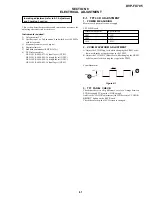
Страница 62: ...DVP FX705 6 7 6 8 3 C Fig 8 3 C L403 MEMO ...

Страница 63: ...1 83 1 52 98 3 2 7 138 3 27 3 1 178 3 32 3 32 218 0 1 1 19 2 05 0 59 0 1 63 99 3 2 7 139 3 2 63 179 2 75 0 219 0 0 20 2 05 0 60 0 2 99 100 2 97 2 67 140 3 2 3 1 180 0 0 220 0 0 21 2 05 0 61 0 0 101 0 2 68 141 3 3 3 3 181 0 0 221 1 76 1 76 22 2 38 0 62 0 0 102 3 33 3 32 142 2 9 2 38 182 3 3 3 3 222 0 1 24 23 3 29 0 63 0 2 05 103 3 33 3 32 143 1 59 1 7 183 0 0 223 0 0 24 3 3 3 3 64 0 0 104 3 2 7 144...

Страница 64: ...19 0 2 0 2 90 0 0 19 4 92 4 92 20 0 0 20 2 32 0 20 1 82 1 64 20 1 78 1 6 20 0 0 20 10 43 10 4 1 0 14 0 14 4 15 15 20 0 2 0 2 91 3 26 3 26 20 4 95 4 95 21 0 0 21 1 64 1 79 21 1 87 1 19 21 10 53 10 4 2 9 08 9 08 5 4 4 21 0 51 0 51 92 1 53 1 53 21 2 3 2 3 22 4 97 4 36 22 0 05 0 06 22 1 91 2 4 PIN STOP PLAY 22 0 0 05 3 9 33 9 33 6 4 4 22 0 06 0 06 93 1 72 1 72 22 4 98 4 98 PIN STOP PLAY 23 2 32 2 29 2...

Страница 65: ...er monitor input 21 MDI2 I Laser power monitor input 22 LDO2 O DVD Laser drive output 23 LDO1 O CD Laser drive output 24 SVDD3 A 3 3V Servo 25 CSO RFOP I Positive input of RF differential signal 26 RFLVL RFON I negative input of RF differential signal 27 SGND Ground pin Servo 28 V2REFO O Reference voltage 2 8V 29 V20 O Referenc voltage 2 0V 30 VREFO O Reference voltage 1 4V 31 FEO I Focus error in...

Страница 66: ...M write enable active low 67 A16 I O A16 FROM address 15 68 HIGHA7 I O A15 FROM address 14 69 HIGHA6 I O A14 FROM address 13 70 HIGHA5 I O A13 FROM address 12 71 HIGHA4 I O A12 FROM address 11 72 HIGHA3 I O A11 FROM address 10 73 DVDD3 D 3 3V 74 HIGHA2 I O A10 FROM address 9 75 HIGHA1 I O A9 FROM address 8 76 IOA20 I O A20 FROM address 19 77 IOCS O PCE FROM Cjip enable 78 IOA1 I O A1 FROM address ...

Страница 67: ... data 6 118 RD5 I O DQ5 DRAM data 5 119 DVSS Ground pin 120 RD4 I O DQ4 DRAM data 4 121 RD3 I O DQ3 DRAM data 3 122 DVDD18 D 1 8V 123 RD2 I O DQ2 DRAM data 2 124 RD1 I O DQ1 DRAM data 1 125 RD0 I O DQ0 DRAM data 0 126 RD15 I O DQ15 DRAM data 15 127 DVDD3 D 3 3V 128 RD14 I O DQ14 DRAM data 14 129 RD13 I O DQ13 DRAM data 13 130 RD12 I O DQ12 DRAM data 12 131 RD11 I O DQ11 DRAM data 11 132 RD10 I O D...

Страница 68: ...Ground pin 164 RA6 O MA6 DRAM address 6 165 RA5 O MA5 DRAM address 5 166 RA4 O MA4 DRAM address 4 167 DVDD3 D 3 3V 168 RD31 ASDATA5 O N C 169 RD30 O RSTB TFT LCD drive IC chip reset 170 RD29 O LCD_MUTE TFT LCD mute control 171 RD28 O N C 172 RD27 N C 173 DVDD18 D 1 8V 174 RD26 O SP_MUTE Speaker mute control 175 DVSS Ground pin 176 RD25 O N C 177 RD24 O SP_AMP_EN Headphone mute control 178 DQM3 O P...

Страница 69: ...serial clock 215 ACLK I ACLK Audio DAC master clock 216 DVSS Ground pin 217 ASDATA0 O ASDATA0 Audio serial data0 left right channel 218 ASDATA1 N C 219 ASDATA2 N C 220 ASDATA3 O A_MUTE LINE Headphone audio mute 221 DVDD18 D 1 8V 222 ASDATA4 O VRST DAC reset control 223 DVSS Ground pin 224 MC_DATA O V_MUTE Y C V mute control 225 SPDIF O ASPDIF SPDIF output Fixed at Open 226 RFGND18 Ground pin 227 R...

Страница 70: ...upling 247 HRFZC I High frequency RF ripple zero crossing 248 CRTPLP I Defect level filter capacitor connecting For RF RIPPLE 249 RFGND Ground pin 250 CEQP N C 251 CEQN N C 252 OSP O RF Offset cancellation capacitor connecting 253 OSN O RF Offset cancellation capacitor connecting 254 RFGC O RF AGC loop capacitor connecting for DVD ROM 255 IREF I Current reference input It generates reference curre...

Страница 71: ...nal 20 RC5 SIN I VFD_TXD Main maicon IC501 communication signal 21 RC6 SOUT O VFD_RXD Main maicon IC501 communication signal 22 RC7 N C 23 RD0 INT2 I The wakeup signal input by DC and Battery voltage 24 RD1 INT3 I REMOCON CONTROL Remote controller signal input 25 RD2 N C 26 RD3 N C 27 RD4 N C 28 RD5 N C 29 RD6 N C 30 RD7 N C 31 XIN I Connecting crystal resonator for main system click oscillation 5...

Страница 72: ...7 8 E MEMO ...

Страница 73: ... 1 POWER MEASURING Measure each power after power supply TFT LCD Board Measurement point Specification L807 15V L806 17V L810 8 25V 2 VCOM WAVEFORM ADJUSTMENT A Adjust the VCOM Vpp level while changing the VR801 as be low waveform by using the scope in the TP8F2 B Adjust the VCOM DC Offset level while changing the VR803 as below waveform by using the scope in the TP8F2 Vcom Waveform Figure 8 1 3 T...

Страница 74: ...th a S terminal cable Mode Play Signal Check the Color bar 100 signal on DVD reference disc Measurement Point S VIDEO OUT S Y connector 75 Ω terminated Measuring Instrument Oscilloscope Specification 1 00 0 05 Vp p Checking method 1 Confirm that the S Y level is 1 00 0 05 Vp p Figure 8 3 8 2 STANDARD VIDEO LEVEL 1 Checking Video Output Level Purpose This checks whether Video Output level satisfy t...

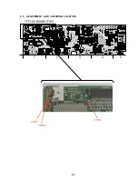
Страница 75: ...8 3 8 3 ADJUSTMENT AND CHECKING LOCATION TFT LCD BOARD TOP A 05 2 1 3 4 5 VR801 TP8F2 VR803 ...

Страница 76: ...8 4 E MEMO ...

Страница 77: ...BATTERY Is ADAPTOR OUT 9 8V Is BATTERY OK Is F101 OK Is LF101 OK Replace F101 YES Is D105 OK Replace D105 Replace ADAPTOR NO 1 8V Is Q102 OK NO 5V NO 5V NO 3 3V NO LCD POWER Replace Q102 Is E 5V OK Replace IC101 Replace IC101 Is Q108 OK Is Q109 OK Replace Q109 Replace Q108 Replace IC102 Is D104 OK Replace D104 Replace BATTERY Replace LF101 NO NO YES ...

Страница 78: ...heck Signals from MPEG Replace IC301 Check Video Jack Mode Check Video signals from MPEG Check LC Filter SPEAKER ABNORMAL Is Q305 OK Is VR300 OK Replace Q305 Replace VR300 Is Speakers OK Replace Speakers Replace IC306 B Audio Out abnormal C Video Out abnormal D Speaker abnormal ...

Страница 79: ...Check MPEG IC501 Replace B D PICTURE ABNORMAL Check Disc YES If OK YES If OK Refer to Servo part Replace B D DISC ERROR Check SW501 switch Check IC501 pin99 YES NO YES YES If OK YES Refer to SERVO part Check the connection of MD OPEN CLOSE ABNORMAL E Picture abnormal G Open Close abnormal F Disc Error ...

Страница 80: ...oder Does the moving picture of the video CD play on the screen normally Does the audio sound output normally END Check power clock Check CD DVD DSP output signal Check MPEG Decoder input signal Check CD DVD DSP output signal Check MPEG Decoder input signal Check CD DVD DSP output signal Check MPEG Decoder input signal Check clock signal Check clock signal YES YES YES YES YES YES YES YES YES YES N...

Страница 81: ...rmal Check SW707 Check waveform of SW707 Does pulse waveform of RC701 Pin 1 appear Is IC701 Pin 24 connected to RC701 Pin1 Is RC701 Pin3 5V Power on Check R746 R747 R756 R749 R750 and replace Check the buttons Solder defective parts Replace IC701 Solder Key part Check Power Replace IC702 Replace SW707 Replace RC701 Re solder Recheck Replace IC701 Complete repairing Front B D NO NO NO NO NO NO NO N...

Страница 82: ... on MT1389 RFL signal Laser off Proper RFL signal on MT1389 Proper DMSO signal on MT1389 Check DMSO related circuit on MT1389 Check the cable connection between spindle and main PCBA Check the RFL connection between CON200 and MT1389 Put disc in Disc ID is correct Does spindle rotate D ...

Страница 83: ...d Proper FO FO signal on MT1389 Proper FOSO signal on MT1389 Check the related circuit on MT1389 FO FO sugnal Check the related circuit on MT1389 Properly TRSO signal on MT1389 TR TR output properly Check the TRSO connection on MT1389 and motor dirver Check the tracking control amp circuit on motor driver Check cable connection on pick up head Check RF signal waveform Check IC501 IC D ...

Страница 84: ... stream Normal Audio DAC out IC301 Check Audio filter amplify mute circuit IC301 Application circuit Check connection between MT1389 Audio DAC Check VRST ACLK ABCK ASDAT0 Check the related circuit of Audio DAC Check Audio out Pin 14 15 18 19 ...

Страница 85: ...9 9 Chargeing Circuit No turn on 8 25V 17V 15V Is J601_Pin1 OK Is L601 C613 C614 R610 OK Is Q601 OK Is IC601 OK Replace L601 C613 C614 R610 Replace Q601 Replace IC601 ...

Страница 86: ...8 25V 17V 15V Check and Replace T801 D8F1 D8F2 D8F3 Check Main B D on located IC901 Check and Replace Key B D Located IC801 IC804 Check Q8F1 Normal operate 8 8V 16V 10V Normal 5V Normal 3 3V 2 5V Normal YES YES NO NO NO NO YES YES YES X801 Replace IC801 Check and Replace IC802 IC803 Check and Replace X801 operate R G B signal output VCOM signal 4 6Vpp NO NO NO YES YES YES ...

Страница 87: ...IDEO_Y VIDEO_C IC501 Key B D Check IC501 Key B D Check SDA SCL signal TFT LCD Normal Replace Color Bright Adjusting Normal IC801 Check Each CONNECTOR Replace and Reassemble INVERTOR Normal Replace END YES YES YES YES YES YES NO NO NO NO NO NO ...

Страница 88: ...9 12 E MEMO ...

Страница 89: ...VIEWS 10 1 1 LCD PANEL SECTION Ref No Part No Description Remark Ref No Part No Description Remark 277 9 885 075 41 SPEAKER FULLRANGE 290 9 885 090 60 TFT LCD PANEL 454 9 885 075 42 TP1 7X4 H10 A41 9 885 090 61 CASE MAIN A41 290 A49 A44B 454 454 277 not supplied not supplied not supplied not supplied not supplied not supplied not supplied A44 not supplied not supplied not supplied not supplied A44...

Страница 90: ...COVER HINGE R 268 9 885 050 57 KNOB OPEN CLOSE 269A 9 885 050 58 LEVER EJECT 269B 9 885 050 59 PLATE LEVER EJECT 292 A 1138 397 A DOOR ASSY 451 9 885 090 51 TP1 7X4 453 9 885 050 38 TP1 7X4 A43B A 1138 396 A CASE TOP ASSY 268 262 263 292 260 451 266 A43B 453 451 451 not supplied not supplied not supplied not supplied not supplied not supplied not supplied not supplied not supplied not supplied 269...

Страница 91: ...A00 021 021 021 A46A A50 809 452 452 not supplied not supplied A46A A 1138 399 A MAIN BOARD ASSY A48 A 1138 400 A CASE BOTTOM ASSY A50 A 1138 395 A KEY BOARD ASSY Les composants identifiés par une marque 0 sont critiquens pour la sécurité Ne les remplacer que par une pièce portant le numéro spécifié The components identified by mark 0 or dotted line with mark 0 are critical for safety Replace only...

Страница 92: ... 049 33 SWITCH TACT DOWN SW912 9 885 049 33 SWITCH TACT UP SW913 9 885 049 33 SWITCH TACT RIGHT SW914 9 885 049 33 SWITCH TACT LEFT SW915 9 885 049 33 SWITCH TACT PUSH ENTER A 1138 399 A MAIN BOARD ASSY DIODE D101 9 885 048 81 DIODE UDZS16B D102 9 885 048 81 DIODE UDZS16B D104 9 885 075 04 DIODE RB050L 40 D105 9 885 075 04 DIODE RB050L 40 D106 9 885 091 24 DIODE RB521G 30 D107 9 885 091 25 DIODE R...

Страница 93: ... 9 885 039 74 TRANSISTOR KTC3875S 0 Q601 9 885 075 23 TRANSISTOR SI4435DY Q701 9 885 049 15 TRANSISTOR KTA1504S Y Q702 9 885 039 74 TRANSISTOR KTC3875S 0 Q703 9 885 039 74 TRANSISTOR KTC3875S 0 Q704 9 885 039 74 TRANSISTOR KTC3875S 0 Q705 9 885 039 74 TRANSISTOR KTC3875S 0 Q706 9 885 050 28 TRANSISTOR 2N7002E Q707 9 885 049 15 TRANSISTOR KTA1504S Y Q708 9 885 049 15 TRANSISTOR KTA1504S Y 0Q8F1 9 8...

Страница 94: ...ER 9 885 049 44 CABLE DIN RCA AUDIO VIDEO 0 9 885 090 86 ADAPTOR AC DC AC FX105 0 9 885 090 87 BATTERY LITHIUM NP FX105 0 9 885 090 88 ADAPTOR DC DCC FX105 The components identified by mark 0 or dotted line with mark 0 are critical for safety Replace only with part number specified Les composants identifiés par une marque 0 sont critiques pour la sécurité Ne les remplacer que par une pièce portant...

Страница 95: ... 126 DVP FX705 Sony Corporation Home Electronics Network Company 9 874 884 11 2005G0500 1 2005 7 Published by Quality Assurance Dept ...

Отзывы: