background image

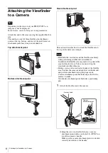
Attaching the Viewfinder to a Camera

7

2

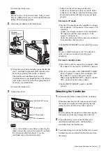
Secure the fixing screw.

Be sure to use a 1/4-inch screw hole. Using a screw 
hole of a different size may result in the flexible arm 
falling off and causing injuries.

2

Attach the viewfinder to the flexible arm.

1

Align the screw and positioning pin on the flexible 
arm’s viewfinder attachment point with the screw 
hole and positioning hole on the viewfinder.
The flexible arm attachment point on the 
viewfinder has two positioning holes to the left and 
right of the screw hole. Select the appropriate hole 
based on your intended use.

2

Secure the fixing screw.

3

Connect the cables.

• Always turn off the camera before connecting the 

cables to the connectors on the camera. If you make 
the connection while the camera is on, the 
viewfinder may not function properly.

• Fully insert the cable connectors into the 

connectors and make sure they are secure. If the 
connector is not firmly connected, the image may 
be distorted and the tally indicator may not light 
properly.

For use in VF mode

1

Use the VF connection cable (supplied) to connect 
the viewfinder’s VF connector to the camera’s VF 
connector.
Connect the straight connector to the viewfinder’s 
VF connector and the angle connector to the 
camera’s VF connector.
Verify the orientations of the connectors, and insert 
them until they click into place.

2

Set the INPUT SELECT switch to the VF position.

Be sure to check the shape of the VF connection 
cable’s connector, and insert it in the proper 
orientation.

For use in monitor mode

1

Use a BNC cable to connect the viewfinder’s SDI 
IN connector to the camera’s SDI OUT connector.

2

Use the power cable (with “STRAIGHT CABLE” 
label) (supplied) to connect the viewfinder’s DC 
IN connector to an external power supply.
When using the PMW-F5/F55, connect to the DC 
OUT connector on the battery adaptor.

3

Set the INPUT SELECT switch to the SDI 
position.

Detaching the Viewfinder

1

Disconnect the cables connected to the viewfinder.

When disconnecting the VF connection cable, pull 
the connector straight out while pressing the lock 
release buttons on both sides of the connector.

Forcibly pulling the connector without pressing the 
lock release buttons may damage the connector.

2

Loosen the fixing screw on the flexible arm’s 

viewfinder attachment point, and detach the 

viewfinder from the flexible arm.

3

Loosen the fixing screw on the flexible arm’s camera 

attachment point, and detach the flexible arm from 

the camera.

Note

Notes

2

1

Viewfinder 
attachment point

SDI IN connector

INPUT SELECT switch

VF connector

DC IN connector

Note

Note

Содержание DVF-L700

Страница 1: ...LCD Color View Finder 4 460 309 13 1 2013 Sony Corporation Operating Instructions Before operating the unit please read this manual thoroughly and retain it for future reference DVF L700 ...

Страница 2: ... Contents Overview 3 Usage Notes 3 Parts Identification 4 Attaching the Viewfinder to a Camera 6 Detaching the Viewfinder 7 Adjusting the Position 8 Adjusting the Display 8 Error Messages 9 Cleaning the Screen 9 Specifications 10 ...

Страница 3: ...u turn on the power Condensation If the unit is suddenly taken from a cold to a warm location or if ambient temperature suddenly rises moisture may form on the outer surface of the unit and or inside of the unit This is known as condensation If condensation occurs turn off the unit and wait until the condensation clears before operating the unit Operating the unit while condensation is present may...

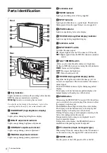
Страница 4: ...llows you to adjust the tally indicator s brightness Set this to OFF when you are not using the tally indicator HIGH Increases the brightness LOW Decreases the brightness OFF Turns the indicator off nFOCUS MAG magnified display button Magnifies the height and width of the image x2 for easier focus adjustment This does not affect the camera s output signal The FOCUS MAG indicator lights during magn...

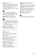
Страница 5: ...n the camera using a BNC cable For details on supported formats see Specifications page 10 u minus button Use this after pressing the BRIGHT CONTRAST or PEAKING button to change the respective value v plus button Use this after pressing the BRIGHT CONTRAST or PEAKING button to change the respective value wPEAKING adjustment button Allows you to emphasize the outlines in the image This does not aff...

Страница 6: ...he viewfinder and the flexible arm firmly when performing attachment or detachment In addition the flexible arm may move at its joints if the arm lock knob is loose Take care not to drop the viewfinder and flexible arm Fixing screws are located on both ends of the flexible arm Confirm the camera end and the viewfinder end and perform attachment using the proper ends Camera attachment point Include...

Страница 7: ...r s VF connector and the angle connector to the camera s VF connector Verify the orientations of the connectors and insert them until they click into place 2 Set the INPUT SELECT switch to the VF position Be sure to check the shape of the VF connection cable s connector and insert it in the proper orientation For use in monitor mode 1 Use a BNC cable to connect the viewfinder s SDI IN connector to...

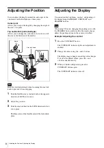
Страница 8: ... knob in the LOCK direction to lock it into place The three joints of the flexible arm will be locked into place Adjusting the Display You can adjust the brightness contrast and peaking of the display using the BRIGHT CONTRAST and PEAKING buttons When using VF mode changing the peaking value with the PEAKING button will not affect the display image unless the peaking setting on the camera is enabl...

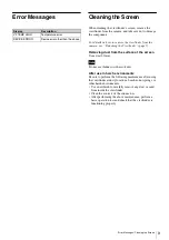
Страница 9: ...Do not use thinner or other solvents After use in harsh environments Be sure to perform the following maintenance after using the viewfinder at dusty locations beaches hot springs or other harsh environments Use an airbrush to carefully remove any dust or sand from inside the viewfinder Clean the contacts of the connectors After performing the above maintenance perform a basic operation test and c...

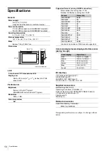
Страница 10: ...0 cd m2 typical Resolution 1920 1080 Color temperature D65 Unit mm inches 127 5 194 7 3 4 52 2 1 8 Supported formats during HD SDI connection Total number of scanning lines 1125 Number of effective scanning lines 1080 Horizontal resolutions of 2048 are not supported VF 26 pin rectangular type 1 SDI IN BNC type 1 MONITOR OUT BNC type 1 DC IN 4 pin 1 10 5 V to 17 0 V DC Before Using this Unit 1 Oper...

Страница 11: ... OF PRESENT OR PROSPECTIVE PROFITS DUE TO FAILURE OF THIS UNIT EITHER DURING THE WARRANTY PERIOD OR AFTER EXPIRATION OF THE WARRANTY OR FOR ANY OTHER REASON WHATSOEVER SONY WILL NOT BE LIABLE FOR CLAIMS OF ANY KIND MADE BY USERS OF THIS UNIT OR MADE BY THIRD PARTIES SONY WILL NOT BE LIABLE FOR THE TERMINATION OR DISCONTINUATION OF ANY SERVICES RELATED TO THIS UNIT THAT MAY RESULT DUE TO CIRCUMSTAN...

Страница 12: ...Sony Corporation ...

Отзывы: