97
P M 3 3 9 4 , F L U K E & P H I L I P S
c h 4
c h 3
c h 2
c h 1
C H 1 ! 1 0 . 0 V =
C H 2 ! 1 . 0 0 V =
C H 3 ! 5 0 . 0 V = B W L
C H 4 ! 1 0 . 0 V = A L T M T B 5 . 0 0 u s - 0 . 6 6 d v c h 1 +
1
2
3
4
T
P M 3 3 9 4 , F L U K E & P H I L I P S
c h 4
c h 3
c h 2
c h 1
c h 3 : p k p k = 7 . 0 7 V
c h 4 : p k p k = 1 . 8 8 V
C H 1 ! 5 . 0 0 V =
C H 2 ! 5 . 0 0 V =
C H 3 ! 5 . 0 0 V = B W L
C H 4 ! 5 0 0 m V = A L T M T B 5 . 0 0 u s - 0 . 6 6 d v c h 1 +
1
2
3
4
T
Horizontal Output PWM 1
The purpose of the Horizontal Output PWM stage is to manufacture a
regulated B+ source for the Horizontal Output transistor. This first part of
the H. Output PWM circuit manufactures a pulse that occurs when the
beam is at the middle of the screen. This pulse is later used for B+ regu-
lation, so its correction (regulation) actually takes place on screen time.
This is not evident in the picture.
The reason the pulse is delayed is to shut off the horizontal output transis-
tor before the next cycle. This is why the correction pulse occurs in the
middle of the screen. Horizontal Output transistor Q4018’s large base
current when the transistor is ON prevents it from cutting off immediately
upon the falling edge of the drive pulse. This delay in cutoff is anticipated
and the position of the correction (also an OFF) pulse is set in order to
ensure transistor cutoff before the next drive pulse.
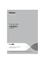
The following scope shot shows the PWM processing, starting with a hori-
zontal drive pulse (ch 1). After shifting (ch 2), a regulation correction pulse
(ch 3) occurs in the middle of the picture between the FBT pulses (ch 4).
W a v e f o r m H D 1 b – P W M M a n u f a c t u r e
N a m e
L o c a t io n
V o lt a g e / d iv
C h a n n e l 1
H D r iv e
C N 4 0 0 9 / p in 1 0
1 2 V p - p
C h a n n e l 2
D e la y e d d r iv e
C N 4 0 0 9 / p in 9
1 . 2 V p - p
C h a n n e l 3
P W M O u t p u t
Q 4 0 2 2 / d r a in
1 4 4 V p - p
C h a n n e l 4
R e f F B T p u ls e
F B T
N / A
T im e b a s e
5 u s e c / d iv
Horizontal Drive Pulse First Delay
Monostable multivibrator (MMV) IC1704/pins 2-13 and comparators IC1705/
pins 1-7 perform the first delay. The output at CN1303/pin 9 is a delayed
low going pulse.
The details can be seen in the waveforms of the following scope shot and
are explained below:
W a v e f o r m H D 1 c – F ir s t D e la y
N a m e
L o c a t io n
V o lt a g e / d iv
C h a n n e l 1
H . D r iv e
I C 1 7 0 4 / p in 2
5 V p - p
C h a n n e l 2
I s t M M V O u t p u t
I C 1 7 0 4 / p in 1 3
5 V p - p
C h a n n e l 3
C a p c o u p le d
I C 1 7 0 5 / p in 7
7 V p - p
C h a n n e l 4
1
s t
D e la y e d p u ls e
I C 1 7 0 5 / p in 1
1 . 8 8 V p - p
T im e b a s e
5 u s e c / d iv
The horizontal drive signal is input at IC1704/pin 2 (ch 1). This monostable
multivibrator is triggered by the leading edge of the drive signal and cre-
ates an output pulse (ch 2). The pulse width is dependent upon the RC
values at IC1704/pins 14 and 15. The second pulse is coupled to com-
parator IC1705/pin 7 (ch 3) through C1709. The charging and discharging
of C1709 forms the peaks of this waveform.
R1732 and R1747 form a voltage divider that prebiases the input of the
comparator IC1705/pin 7 (ch 3). The prebiasing permits only the delayed
bottom peaks of the input waveform to produce an output pulse at IC1705/
pin 1. This low going output pulse is delayed from the original horizontal
drive signal and is applied to the second delay circuit on the D board via
CN1303/pin 9.
Содержание DTV-01
Страница 1: ...S Training Manual Circuit Description and Troubleshooting Course DTV 01 High Definition Television ...
Страница 15: ...18 NOTES ...
Страница 23: ...26 ...
Страница 25: ...28 ...
Страница 27: ...30 ...
Страница 29: ...32 ...
Страница 31: ...34 ...
Страница 33: ...36 ...
Страница 37: ...20 NOTES ...
Страница 41: ...44 ...
Страница 43: ...46 ...
Страница 45: ...48 ...
Страница 47: ...50 ...
Страница 49: ...52 ...
Страница 51: ...54 ...
Страница 53: ...56 ...
Страница 55: ...58 ...
Страница 57: ...60 ...
Страница 59: ...62 ...
Страница 61: ...64 ...
Страница 63: ...66 ...
Страница 65: ...68 ...
Страница 67: ...70 ...
Страница 69: ...72 ...
Страница 71: ...74 ...
Страница 73: ...76 ...
Страница 75: ...78 ...
Страница 77: ...80 ...
Страница 79: ...82 ...
Страница 81: ...84 ...
Страница 83: ...86 ...
Страница 85: ...88 ...
Страница 87: ...90 ...
Страница 89: ...92 ...
Страница 91: ...94 ...
Страница 93: ...96 ...
Страница 95: ...98 ...
Страница 97: ...100 ...
Страница 99: ...102 ...
Страница 101: ...104 ...
Страница 103: ...106 ...
Страница 105: ...108 ...
Страница 107: ...110 ...
Страница 109: ...112 ...
Страница 111: ...114 ...
Страница 113: ...116 ...
Страница 115: ...118 ...
Страница 117: ...120 ...
Страница 119: ...122 ...
Страница 121: ...124 ...
Страница 123: ...126 ...
Страница 125: ...128 ...
Страница 128: ...iii ...