


Chapter 1
Overview
Chapter 1
Overview
13
POWER
INPUT SELECT
SDTI/i.LINK
VIDEO IN
REMOTE
9PIN
i.LINK
CH-1,1/2
CH-2,3/4
MIXING
0
2
1
0
-1
-2
-12
dB OVER dB
-20
-30
-40
-60
1
0
2
1
0
-1
-2
-12
dB OVER dB
-20
-30
-40
-60
2
0
2
1
0
-1
-2
-12
dB OVER dB
-20
-30
-40
-60
3
0
2
1
0
-1
-2
-12
dB OVER dB
-20
-30
-40
-60
4
INPUT
V:SDTI
COMPOSITE
ANALOG
AES/EBU
ANALOG
SDTI
SDI SG
SDI SG
AES/EBU
SDI SG
Y-R,B S VIDEO
i.LINK
PB FS
48k44.1k32k
REC MODE
2CH4CH
VIDEO
AUDIO
CH11/2
CH23/4
INPUT
V:SDTI
COMPOSITE
ANALOG
AES/EBU
ANALOG
SDTI
SDI SG
SDI SG
AES/EBU
SDI SG
Y-R,B S VIDEO
i.LINK
PB FS
48k44.1k32k
REC MODE
2CH4CH
VIDEO
AUDIO
CH11/2
CH23/4
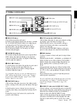
Upper Control Panel
1
POWER switch
2
Audio level meters
3
Cassette compartment
1
Input selection/audio mode display section
(see below)
1
POWER switch
Press the “
1
” side to power the unit on. When the unit
is powered on, the display windows in the upper and
lower control panels light.
To power the unit off, press the “
¬
”side of the switch.
2
Audio level meters
These show the audio levels of channels 1 to 4
(recording levels in recording mode or E-E mode
1)
and
playback level in playback mode).
There are two modes for audio level indications:
FULL and FINE, selected by the METER FULL/FINE
button on the lower control panel.
1) E-E mode: Abbreviation of “Electric-to-Electric mode”.
In this mode, video and audio signals input to the VCR
are output after passing through internal electric circuits,
.........................................................................................................................................................................................
3
Cassette compartment
Accepts DVCAM, DV and DVCPRO(25)
videocassettes.
For details of usable cassettes, see page 33.
1
Input selection/audio mode display section
1
INPUT display
5
PB FS display
6
REC MODE display
2
INPUT VIDEO display
3
AUDIO CH1, CH1/2 display
4
AUDIO CH2, CH3/4 display
but not through magnetic conversion circuits such as
heads and tapes. This can be used to check input signals
and for adjusting input signal levels.
2
Input selection section
(see page 14)
3
Remote control
setting section
(see page 15)


