background image

!

 WARNING

This manual is intended for qualified service personnel only.
To reduce the risk of electric shock, fire or injury, do not perform any servicing other than that
contained in the operating instructions unless you are qualified to do so. Refer all servicing to
qualified service personnel.

!

 WARNUNG

Die Anleitung ist nur für qualifiziertes Fachpersonal bestimmt.
Alle Wartungsarbeiten dürfen nur von qualifiziertem Fachpersonal ausgeführt werden. Um die
Gefahr eines elektrischen Schlages, Feuergefahr und Verletzungen zu vermeiden, sind bei
Wartungsarbeiten strikt die Angaben in der Anleitung zu befolgen. Andere als die angegeben
Wartungsarbeiten dürfen nur von Personen ausgeführt werden, die eine spezielle Befähigung
dazu besitzen.

!

 AVERTISSEMENT

Ce manual est destiné uniquement aux personnes compétentes en charge de l’entretien. Afin
de réduire les risques de décharge électrique, d’incendie ou de blessure n’effectuer que les
réparations indiquées dans le mode d’emploi à moins d’être qualifié pour en effectuer d’autres.
Pour toute réparation faire appel à une personne compétente uniquement.

For the customers in the U.S.A.

Attention-when the product is installed in Rack:

1. Prevention against overloading of branch circuit

When this product is installed in a rack and is
supplied power from an outlet on the rack, please
make sure that the rack does not overload the supply
circuit.

2. Providing protective earth

When this product is installed in a rack and is
supplied power from an outlet on the rack, please
confirm that the outlet is provided with a suitable
protective earth connection.

3. Internal air ambient temperature of the rack

When this product is installed in a rack, please make
sure that the internal air ambient temperature of the
rack is within the specified limit of this product.

4. Prevention against achieving hazardous

condition due to uneven mechanical loading
When this product is installed in a rack, please make
sure that the rack does not achieve hazardous
condition due to uneven mechanical loading.

Содержание DSM-T1

Страница 1: ...DIGITAL SATELLITE MODULATOR DSM T1 INSTALLATION MANUAL 1st Edition Serial No 10001 and Higher ...

Страница 2: ... effectuer que les réparations indiquées dans le mode d emploi à moins d être qualifié pour en effectuer d autres Pour toute réparation faire appel à une personne compétente uniquement For the customers in the U S A Attention when the product is installed in Rack 1 Prevention against overloading of branch circuit When this product is installed in a rack and is supplied power from an outlet on the ...

Страница 3: ... E 1 2 Power Supply 1 1 E 1 2 1 Power Specifications 1 1 E 1 2 2 Power Cord 1 1 E 1 3 External Dimensions and Installation Space 1 2 E 1 4 Matching Connectors and Cables 1 3 E 1 5 Input and Output Signal of Connector 1 3 E 1 6 Internal Switches and Indicators 1 4 E 1 7 Rack Mounting 1 5 E 1 8 Optional Boards 1 7 E 1 9 Setting of Television System 1 8 E ...

Страница 4: ......

Страница 5: ...onment the connector information for peripheral equipment connections etc Related manuals Besides this Installation Manual the following manuals are available for the DSM T1 Operation Manual Supplied with the DSM T1 This manual explains the overview of the DSM T1 the system configuration examples etc Maintenance Manual Not supplied with the DSM T1 This manual describes the information that premise...

Страница 6: ......

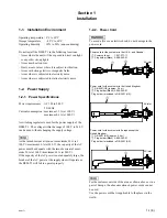
Страница 7: ...at turn on is maximum 30 A at 100 V maximum 60 A at 240 V the capacity of the AC power must be adequate with the inrush current of maxi mum 30 A at 100 V maximum 60 A at 240 V If the capacity of the AC power is not adequately large the breaker of the AC power at the supply side will operate or the DSM T1 will fail to operate properly 1 2 2 Power Cord w To avoid a fire or an electric shock do not d...

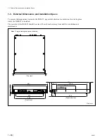
Страница 8: ...SM T1 pay careful attention to circulation of air in the place where the DSM T1 is installed The rear side of the DSM T1 should be at least 10 cm 4 inches away from walls for ventilation and maintenance 525 415 9 14 263 5 123 8 20 5 72 7 435 49 481 465 43 6 10 374 424 Mass 8 kg including two optional boards Top view Front view Right side view Unit mm ...

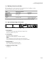
Страница 9: ...commended to use the coaxial cable 5C 2V of Fujikura America Inc Fujikura Europe Ltd FEL or the equivalent 1 5 Input and Output Signal of Connector 1 REF IN BNCx1 External reference video signal input black burst or composite sync Sync level 40 IRE 0 3 V p p 75 Z 2 IF OUT BNCx1 Intermediate Frequency signal output 75 Z 0 _10 _20 dBm selectable 70 140 MHz selectable n The level and frequency of the...

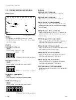
Страница 10: ...01 P 9 red PLL Lock indicator Lights off when the PLL at 4 FSC 14 3 MHz of the internal clock locks with the selected reference signal at 525 system D602 P 10 red PLL Lock indicator Lights off when the PLL at 4 FSC 17 73 MHz of the internal clock locks with the selected reference signal at 625 system D751 N 6 green PLL Lock indicator Lights up when the PLL at 24 576 MHz of the internal clock locks...

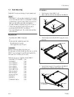
Страница 11: ... Be sure to use the specified rack mount rail If a rack mount rail other than the specified one is used the DSM T1 may be dropped by insufficient strength of the rack mount rail This may cause a injury The following parts are supplied with the DSM T1 Rack angle 1U Assembly 2 pcs Rail bracket 4 pcs Screw K 4x14 4 pcs Screw B 4x14 4 pcs Screw B 4x8 8 pcs Screw B 5x12 8 pcs Screw RK 5x14 4 pcs Plate ...

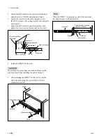
Страница 12: ...ful not to get caught your hand and finger in the rack mount rail when installing the unit in the rack 9 After installing the DSM T1 in the rack secure the unit to the rack using the screws RK 5x14 and ornamental washers Inner rail The maximum traveling distance 580 mm Outer rail Rail bracket Rack The side installed rack angle Rail bracket Plate nut large Outer rail Spec 52 5 mm _0 Rack B 4x8 B 5x...

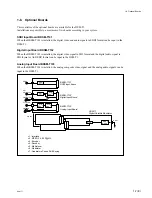
Страница 13: ...gital audio signal in SDI format or AES EBU format can be input in the DSM T1 Analog Input Board BKSM T103 When the BKSM T103 is installed the analog composite video signal and the analog audio signals can be input in the DSM T1 1 8 Optional Boards 4 2 2P 2 ENC 3 4 2 2P 2 ENC 3 A D DEC 4 SDI I F 1 SDDI I F 1 A D MOD 6 QPSK 7 MUX 5 IF OUT DSM T1 Digital Satellite Modulator BKSM T101 SDDI Input Boar...

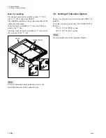
Страница 14: ...de install the rear panel to the 2 side n For more information about installation refer to the Installation Manual of each optional boards IN 2 side IN 1 side DSM T1 Optional boards IN 2 side IN 1 side 1 2 1 2 1 2 1 9 Setting of Television System Be sure to set the television system when the DSM T1 is installed To set the television system select 03 VIDEO STD in the menu 525 60 525 60 NTSC system ...

Страница 15: ...des acquéreurs de l équipement décrit dans ce manuel Sony Corporation interdit formellement la copie de quelque partie que ce soit de ce manuel ou son emploi pour tout autre but que des opérations ou entretiens de l équipement à moins d une permission écrite de Sony Corporation Das in dieser Anleitung enthaltene Material besteht aus Informationen die Eigentum der Sony Corporation sind und ausschli...

Страница 16: ...Printed in Japan Sony Corporation 1998 1 16 Broadcasting Professional Systems Company 1998 Published by Global Support Promotion Dept DSM T1 SY J E 3 200 066 01 ...

Отзывы: