background image

— 12 —

2-5.

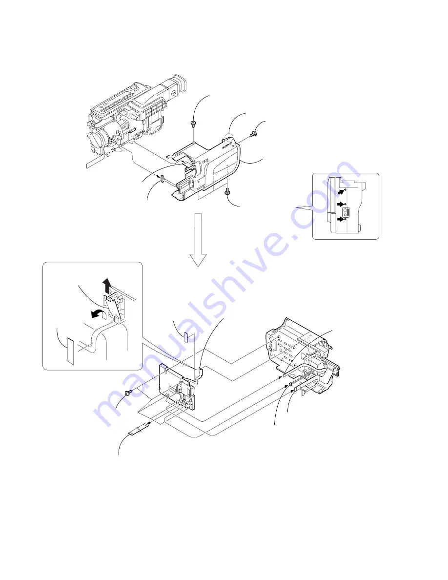
CABINET (R) SECTION, CONTROL SWITCH BLOCK (CF-1000)

1

 MI screw 

     (M2 

×

 4) (H)

2

 MI screw 

     (M2 

×

 4) (H)

4

 Claw

3

 Three MI screws 

     (M2 

×

 4) (H)

6

 FFC-295 flexible

     flat cable (24P)

1

 FFC-295 flexible flat cable (24P)

2

 FP-260 flexible board (16P)

3

 Electro luminous 

     element (4P)

4

 Push switch (2P)

7

 Cabinet (R) section

5

 Five tapping 

     screws (B2 

×

 5)

5

 Harness

     (PD-110) (20P)

8

 Control switch block

     (CF-1000)

6

 Tape (A)

Tape (A)

7

 Remove the control switch block 

     (CF-1000) in the direction of the 
     arrow 

A B

.

A

B

Содержание Digital Handycam DCR-TRV130E

Страница 1: ...AEP Model UK Model SERVICE MANUAL SPECIFICATIONS Level 1 SERVICE MANUAL SERVICE MANUAL DCR TRV130E RMT 814 M2000 MECHANISM DIGITAL VIDEO CAMERA RECORDER Ver 1 0 2001 01 ...

Страница 2: ...ply force on the conductor when soldering or unsoldering SAFETY CHECK OUT After correcting the original service problem perform the following safety checks before releasing the set to the customer Checking supplied accessories Make sure that the following accessories are supplied with your camcorder Wireless Remote Commander 1 RMT 814 1 475 141 61 AC L10A L10B L10C AC power adaptor 1 0 1 475 599 1...

Страница 3: ...sette 26 Recording Basics Recording a picture 26 Shooting backlit subjects BACK LIGHT 28 Shooting in the dark NightShot Super NightShot 28 Checking the recording END SEARCH 29 Playback Basics Playing back a tape 29 Viewing the recording on TV 31 Advanced Recording Operations Recording a still image on a tape Tape Photo recording 31 Using the wide mode 32 Using the fader function 32 Using special e...

Страница 4: ...fer to 2 3 to remove the front panel section 2 Refer to 2 4 to remove the cabinet L section 3 Refer to 2 5 to remove the cabinet R section 4 Open the control switch block FK 1000 5 Disconnect CN4401 2P of VC 256 board 6 Add 5V from the DC POWER SUPPLY and unload with a pressing the cassette compertment 8 Let your hold the cassette compartment and rise the cassette compartment to take out a cassett...

Страница 5: ...y Method While pressing the STOP key set the switch from OFF to VCR or PLAYER and continue pressing the STOP key for 5 seconds continuously The service mode will be displayed and the counter will show the backup No and the 5 character self diagnosis codes 3 2 Switching of Backup No By rotating the control dial past self diagnosis codes will be shown in order The backup No in the indicates the orde...

Страница 6: ...rm operations from the beginning Load the tape again and perform operations from the beginning Load the tape again and perform operations from the beginning Load the tape again and perform operations from the beginning Load the tape again and perform operations from the beginning Load the tape again and perform operations from the beginning Load the tape again and perform operations from the begin...

Страница 7: ...Inspect the lens block focus reset sensor Pin qs of CN1551 of VC 256 board when focusing is performed when the control dial is rotated in the focus manual mode and the focus motor drive circuit IC1551 of VC 256 board when the focusing is not performed Inspect the lens block zoom reset sensor Pin qf of CN1551 of VC 256 board when zooming is performed when the zoom lens is operated and the zoom moto...

Страница 8: ...uch as a cabinet are also appeared in this section Refer to the parts number mentioned below the name of parts to order 1 ORNAMENTAL PARTS The components identified by mark 0 or dotted line with mark 0 are critical for safety Replace only with part number specified DCR TRV130E Video light 1 518 723 21 Jack cover 3 065 433 01 Lens cap assembly X 3949 376 1 CPC lid 3 059 539 11 Remote commander RMT ...

Страница 9: ... light 2 2 LCD section PD 131 board 2 3 Front panel section MI 041 board 2 4 Cabinet L section 2 7 Battery panel section Battery terminal board 2 8 Lens section 2 9 VC 256 board 2 10 Mechanism deck 2 5 Cabinet R section Control switch block CF 1000 2 6 EVF section VF 129 board 2 11 Hinge section ...

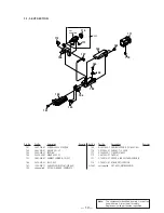
Страница 10: ... inside hole with wire tip 2 Video light A 3 Remove in the direction of the arrow A 4 Halogen lamp P D 1 3 1 A A 1 Two tapping screws B2 5 6 P cabinet M assembly 5 Two tapping screws B2 7 2 MI screw M2 4 H 4 P cabinet C 3 Five claws 7 Liquid crystal indicator module 8 Back light Cold cathode fluorescent tube 9 PD 131 board Panel frame ...

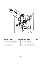
Страница 11: ...crophone retainer rear 4 Microphone retainer front 7 Front panel section 6 FP 263 flexible board 24P 3 Two tapping screws B2 5 2 Microphone Lch 2P 6 Microphone Lch 5 Microphone Rch 4 MI 041 board 1 Two tapping screws B2 5 1 Microphone Rch 2P 2 Two MI screws M2 4 H 6 Two MI screws M2 4 H 4 MI screw M2 4 H 5 MI screw M2 4 H 7 MI screw M2 4 H 8 Cabinet L section 3 Cassette lid assembly 1 ...

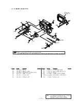
Страница 12: ...295 flexible flat cable 24P 1 FFC 295 flexible flat cable 24P 2 FP 260 flexible board 16P 3 Electro luminous element 4P 4 Push switch 2P 7 Cabinet R section 5 Five tapping screws B2 5 5 Harness PD 110 20P 8 Control switch block CF 1000 6 Tape A Tape A 7 Remove the control switch block CF 1000 in the direction of the arrow AB A B ...

Страница 13: ...ape A 4 4 Tape A 3 VF base B 1 F lock screw T 1 2 Slide the button in the direction of the arrow A 2 Two tapping screws B2 5 5 Tapping screw B2 5 6 EVF tally 7 EVF cabinet lower B 3 Claw 8 CRT assembly VF 129 board FFC 289 flexible flat cable 4 EVF cabinet upper B assembly A B C 3 Finder S assembly Rotate it in the direction of the arrow B and remove it in the direction of the arrow C PRECAUTION D...

Страница 14: ...om lens block 24P 4 Two screws M2 3 lock ace p2 5 Claw 6 1 Two tapping screws B2 5 2 Lens frame 3 Lens section 3 MI screw M2 4 H 1 MI screw M2 4 H 3 Battery terminal board 2 Strap sheet metal lower 4 MI screw M2 4 H 6 Battery panel section 7 Control switch block SS 1000 5P 2 Battery terminal board 7P 1 Tripod screw 5 Claw 2 8 LENS SECTION ...

Страница 15: ...FP 258 flexible board 4 Jack cushion 3 Two screws M2 3 lock ace p2 2 MD frame B 7 Control switch block FK 1000 12P D A B A B C D C 2 Two claws 3 Three dowels 1 Screw M2 3 lock ace p2 1 Three screws M1 7 2 5 p 2 absorbing sheet 5 MD sheet 4 MD frame A 3 4 Control switch block FK 1000 6 Mechanism deck REMOVING THE MECHANISM DECK ...

Страница 16: ...e blind Push switch 4 Three tapping screws B2 5 3 Electro luminous element 4P 1 Four tapping screws B2 5 2 7 Control switch block PR 10000 6 Screw M1 7 2 5 p 1 Four claws 2 Hinge cover C 3 Hinge cover M 4 Harness clamp 8 Hinge assembly 5 Harness PD 110 REMOVING THE HINGE ASSEMBLY ...

Страница 17: ...INER FRONT MICROPHONE 4 3 065 470 01 CUSHION 10 MICROPHONE 5 X 3951 220 1 PANEL 10 ASSY F 6 3 067 347 01 MI SCREW M2 H 7 1 518 723 21 LIGHT VIDEO 8 X 3949 376 1 CAP N ASSY LENS 9 3 065 433 01 COVER 10 JACK 10 X 3951 194 1 CABINET L 10 ASSY 11 3 052 815 01 BELT ES GRIP 12 3 065 455 01 STOPPER FRONT 10 BELT 13 3 065 457 01 PLATE REAR 10 L GROUND 14 3 058 622 01 STOPPER REAR BELT 15 not supplied MI 0...

Страница 18: ...TRAP 61 3 066 169 01 SHEET MD 62 1 476 424 41 SWITCH BLOCK CONTROL SS 1000 63 X 3951 196 1 PANEL 12 ASSY BATTERY 64 3 987 656 01 LID JACK 65 not supplied VC 256 IB S BOARD COMPLETE SERVICE 66 3 948 339 61 TAPPING 67 1 680 200 11 FP 259 FLEXIBLE BOARD 68 3 065 662 01 LABEL LS CAUTION 69 3 941 343 21 TAPE A 70 3 067 254 01 SHEET 10 ABSORBING 71 3 066 949 01 CUSHION 12 JACK BT901 1 694 384 11 TERMINA...

Страница 19: ...FLAT FFC 289 108 not supplied VF 129 P BOARD COMPLETE 109 X 3951 202 1 CABINET UPPER B 12 ASSY EVF 110 3 975 898 01 SCREW T F LOCK 111 X 3949 329 1 FINDER S ASSY 112 3 941 343 21 TAPE A 113 3 709 272 01 COVER HIGH VOLTAGE SERVICE 114 3 709 273 01 MASK CRT SERVICE 0V901 not supplied CRT ASSY M01KXX90WB Note The components identified by mark 0 or dotted line with mark 0 are critical for safety Repla...

Страница 20: ...56 3 053 827 01 LEVER IR 157 3 053 800 01 SPRING RETAIN 158 3 053 799 01 GEA IR 159 not supplied ADAPTOR FK CCD FITTING 160 not supplied FILTER BLOCK OPTICAL 161 not supplied RUBBER F SEAL 162 not supplied CD 281 X BOARD COMPLETE 163 3 318 203 11 SCREW B1 7X6 TAPPING IC191 not supplied CCD BLOCK ASSY CCD IMAGER M905 not supplied MOTOR STEPPING F630 FOCUS M906 not supplied MOTOR STEPPING Z600 ZOOM ...

Страница 21: ...XIBLE FLAT FFC 295 209 3 941 343 21 TAPE A 0D901 not supplied ELEMENT ELECTRO LUMINOUS LCD902 not supplied DISPLAY PANEL LIQUID CRYSTAL S901 1 771 848 11 SWITCH PUSH Note The components identified by mark 0 or dotted line with mark 0 are critical for safety Replace only with part number specified A A B C B C LCD section See page 22 S901 LCD902 D901 201 201 201 202 201 201 207 208 203 209 204 205 2...

Страница 22: ... 058 672 01 CLAMP HARNESS 254 3 948 339 31 SCREW TAPPING 255 3 065 477 01 COVER C 12 HINGE 256 X 3951 206 1 HINGE 12 ASSY 257 1 960 975 11 HARNESS PD 110 258 3 065 478 01 COVER M 12 HINGE 259 4 974 725 01 SCREW M1 7X2 5 P 260 1 418 802 11 SWITCH BLOCK CONTROL PR 10000 261 not supplied PD 131 XC 2 5 BOARD COMPLETE 262 3 968 729 51 SCREW M2 LOCK ACE P2 263 3 065 475 01 FRAME 12 PANEL 264 X 3951 199 ...

Страница 23: ...This section is extracted from instruction manual 23 DCR TRV130E 2 GENERAL ...

Страница 24: ... 24 ...

Страница 25: ... 25 ...

Страница 26: ... 26 ...

Страница 27: ... 27 ...

Страница 28: ... 28 ...

Страница 29: ... 29 ...

Страница 30: ... 30 ...

Страница 31: ... 31 ...

Страница 32: ... 32 ...

Страница 33: ... 33 ...

Страница 34: ... 34 ...

Страница 35: ... 35 ...

Страница 36: ... 36 ...

Страница 37: ... 37 ...

Страница 38: ... 38 ...

Страница 39: ... 39 ...

Страница 40: ... 40 ...

Страница 41: ... 41 ...

Страница 42: ... 42 ...

Страница 43: ... 43 ...

Страница 44: ... 44 ...

Страница 45: ... 45 ...

Страница 46: ... 46 ...

Страница 47: ... 47 ...

Страница 48: ... 48 ...

Страница 49: ... 49 ...

Страница 50: ... 50 ...

Страница 51: ... 51 ...

Страница 52: ... 52 DCR TRV130E Sony Corporation Personal VIDEO Products Company 2001A1600 1 2001 1 Published by Safety Service Engineering Dept 9 929 860 41 ...

Страница 53: ...Revision History Ver 1 0 Date 2000 01 History Official Release Contents S M Rev issued 992986041 pdf Reverse ...

Отзывы: