


DCR-HC65
2-1
2-2
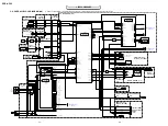
2-1. DISASSEMBLY
The following flow chart shows the disassembly procedure.
SECTION 2
DISASSEMBLY
B
B
B
VC-359
VC-359
C
A
D
B
E
F
G
1
Open the cassette lid.
2
Two screws (M1.7x2.5) silver
3
Two screws (M1.7x2.5) silver
4
Screw (M1.7x2.5) silver
5
Eject knob
6
Cabinet (G) section
1
Open the cassette lid.
2
Two screws (M1.7x4) silver
3
Screw (M1.7x4) silver
4
Three screws (M1.7x2.5) silver
5
Open the LCD panel.
6
Two screws (M1.7x4) silver
7
FP-920 flexible board (51P)
8
Cabinet (R) section
1
Tape (R), fixed
2
Tape (CK), fixed
3
Spacer (R), fixed
1
Screw (M1.7x4) silver
2
Two screws (M1.7x2.5) silver
3
Craw
4
VC radiation plate assembly
5
Harness fixed tape
6
FP-916 flexible board (21P),
Control key block(FK7800)(14P)
7
Raise the Finder
8
Three tapping screws
(M1.7x3.5) silver
9
EVF section
1
Screw (M1.7x4) silver
2
Shield sheet (JK)
3
Two tapping screw
(M1.7x3.5) silver
4
Screw
5
JM-016 board,
JK-268 board,
FP-918 flexible board, etc.
6
Five tapping screws
(M1.7x3.5) silver
7
Control key block (PS7800),
ST bracket (front)
1
FP-913 flexible board (33P),
Flexible board (from lensdevice)(29P)
2
Control key block(PS7800)(10P)
3
Screw (M1.7x4) silver
4
Screw (M1.7x4) silver
5
Two screws (M1.7x2.5) silver
6
Open the cassette lid.
7
FP-918 flexible board (27P)
8
VC-359 board, Mechanism deck,
Cabinet (G) section, etc.
1
Two tapping screws (M1.7x3.5) silver
2
Lens section
1
Open the cassette lid.
2
Screw (M1.7x4) silver
3
FP-912 flexible board (30P)
4
Battery panel section
5
Flexible board (CN9102) (27P)
6
Flexible board (CN9103) (27P)
7
FP-919 flexible board (27P)
8
FP-910 flexible board (6P)
9
Two screws (M1.7x2.5) silver
q;
Flexible board (CN9101) (10P)
qa
Flexible board (CN6501) (10P)
qs
VC-359 board
qd
Four screws (M1.4x1.5) silver
qf
Mechanism deck
1
Screw (M1.7x4) silver
2
Open the jack cover assembly.
3
Screw (M1.7x4) silver
4
Two screws (M1.7x4) silver
5
FP-919 flexible board (28P)
6
Cabinet (F) section
2
3
6
4
5
2
3
5
4
6
1
A
A
A
A
A
2
3
1
B
A
B
C
E
E
F
A
A
A
B
A
C
C
B
B
G
A
B
D
A
B
A
4
6
5
1
2
3
6
3
4
7
1
2
3
8
6
4
4
6
5
8
3
2
1
7
8
a
a
4
5
8
1
2
8
5
9
6
1
4
2
3
C
1
2
7
6
1
2
7
3
1
4
3
q;
qa
qd
8
6
qf
5
9
7
qs
4
1
2
5
7
a
b
a
b
a
4
Harness (PC-131) (10P)
5
Harness (PC-132) (14P)
6
FP-911 flexible board (6P)
7
Two screws (M1.7x4) silver
8
LCD section
5
9
7
1
Four screws (M1.7x4) silver
2
P cabinet (C) assembly (841)
3
Harness (PC-131) (10P)
4
Harness (PC-132) (14P)
5
Two screws (M1.7x2.5) silver
1
VF shield sheet
2
Two tapping screws (M1.7x5) black
3
Remove the EVF block .
4
Two tapping screws (M1.7x5) black
5
Pull out the VF lens assembly in the
direction of the arrow a.
6
Two tapping screws (M1.7x4) black
7
Remove the craw.
8
VF lens assembly.
6
Hinge section
7
Control key block (SB7800) (6P)
8
P cabinet (M) assembly
9
PD-219 board,
LCD unit (ACX531AKM-J),
Light guide plate block
6
7
5
8
Tapping screw
M1.7x3.5
3-078-890-01
Screw
M1.7x4
3-078-893-21
Screw
M1.7x4
3-055-573-21
Tapping screw
M1.7x5
3-080-222-21
Tapping screw
M1.7x4
3-080-222-11
Silver
Black
Screw
M1.7x2.5
3-989-735-01
Special screw
1.4x1.5
3-062-214-01