


DCR-DVD201/DVD201E
2-1
2-2
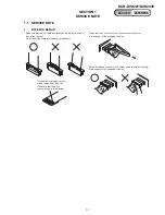
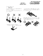
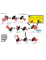
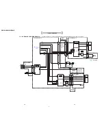
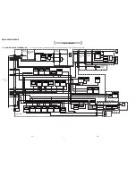
2-1. DISASSEMBLY
The following flow chart shows the disassembly procedure.
VC-354
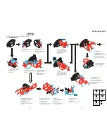
1
2
4
3
2
1
3
5
6
7
9
5
1
Two grip screws (M1.7x3) black
2
Two grip screws (M1.7x3) black
3
Six claws
4
P cabinet (C) assembly
5
Sheet (MY)
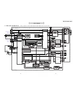
1
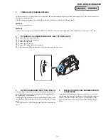
Open the jack cover
2
EG grip Screw (M1.7x4) black
3
EG grip Screw (M1.7x4) black
4
Turn over the EVF section in the
direction of the arrow.
5
EG grip Screw (M1.7x4) black
6
Two EG grip Screws (M1.7x4) black
7
Three EG grip Screws (M1.7x4) black
8
Two EG grip Screws (M1.7x4) black
9
Five claws
0
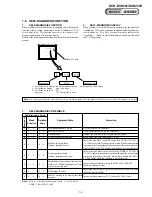
Remove the cabinet (R) section
in the direction of the arrow.
qa
MA-429 board (27P)
qs
F panel section
qd
FP-884 flexible board (33P)
qf
Cabinet (R) section
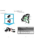
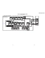
1
Two grip screws (M1.7x3) black
2
Two grip screws (M1.7x3) black
3
Six claws
4
P cabinet (C) assembly
5
FP-890 board (22P)
6
Hinge (87) assembly, Hinge cover (O),
Hinge cover (U), FP-890 board
1
Tape (0915)
2
Three screws (M1.7x2.5) silver
3
FP-892 flexible board (39P)
4
From lens flexible board (29P)
5
Lens section
1
Screw (M1.7x2.5) silver
2
VC heat sink, VC radiation sheet,
VC insulating sheet
3
Three screws (M1.7x2.5) silver
4
Control switch block (PS8700) (20P)
5
Board to board (CN1007, CN4901) (100P)
6
Radiation sheet (135)
7
VC-354 board
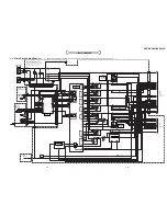
1
Screw (M1.7x2.5) silver
2
EG grip screw (M1.7x4) black
3
FP-883 flexible board (10P)
4
FP-889 flexible board (20P)
5
EVF section
1
Grip screw (M1.7x3) black
2
Four claws
3
Hinge cover (O)
4
Hinge cover (U)
5
Hinge (87) assembly, FP-890 board
7
Sheet (MY)
8
Screw (M1.7x5) black
9
Control switch block (BL8700) (6P)
0
Two claws
qa
P cabinet (M) assembly
qs
PD-220 board, Insulating sheet,
Light guide plate block
qa
qf
qd
0
4
qs
A
A
B
B
B
B
B
B
B
B
2
1
D
3
7
D
1
4
5
2
5
8
5
4
3
1
7
9
qa
2
0
6
qs
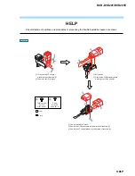
HELP 02
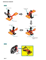
HELP 01
2
3
1
A
A
E
A
4
5
D
3
4
4
3
1
2
5
D
8
See page
2-3.
Screw
M1.7x3
3-084-817-21
Screw
M1.7x2.5
3-078-889-11
Silver
Black
Screw
M1.7x4
3-087-376-01
Tapping screw
M1.7x3.5
3-078-890-01
Tapping screw
M1.7x5
3-081-204-21
A
C
B
D
E
6
1
2
1
Screw (M1.7x2.5) silver
2
Front fixed plate
3
EG grip screw (M1.7x4) black
4
Screw (M1.7x2.5) silver
5
Two tapping screws (M1.7x5) black
6
Claw
7
Remove the cabinet center (M)
assembly in the direction of the arrow.
1
Push this portion with a finger
in the direction of the arrow a.
2
Open the D lid assembly
in the direction of the arrow b.
3
4
5
2
6
B
1
7
D
E
D
1
5
4
2
3
6
1
Two tapping screws (M1.7x3.5) silver
2
Speaker retainer plate assembly
3
Three tapping screws (M1.7x3.5) silver
4
FP-890 board (20P)
5
FP-884 flexible board (8P)
6
Three EG grip screws (M1.7x4) black
7
LCD section
C
C
B
B
7
a
b
SECTION 2
DISASSEMBLY
Содержание DCR-DVD201
Страница 3: ... 3 DCR DVD201 DVD201E ENGLISH JAPANESE ENGLISH JAPANESE ...
Страница 5: ... 5 DCR DVD201 DVD201E ENGLISH JAPANESE ENGLISH JAPANESE ...
Страница 10: ...1 4 DCR DVD201 DVD201E ENGLISH JAPANESE ENGLISH JAPANESE SECTION 1 SERVICE NOTE ...
Страница 11: ...1 5 DCR DVD201 DVD201E ENGLISH JAPANESE ENGLISH JAPANESE ...
Страница 12: ...1 6E DCR DVD201 DVD201E ENGLISH JAPANESE ENGLISH JAPANESE ...
Страница 18: ...Disassembling procedure of MD block assembly are not shown Page 2 10 is not shown ...
Страница 65: ...5 13 DCR DVD201 DVD201E 5 REPAIR PARTS LIST 5 REPAIR PARTS LIST J MODEL ...
Страница 69: ...DCR DVD201 DVD201E 100 Sony EMCS Co 2004B1600 1 2004 2 Published by DI CS Strategy Div 9 876 715 31 ...
Страница 71: ...ENGLISH JAPANESE ENGLISH JAPANESE ...
Страница 72: ...Revision History 987671531 pdf Ver 1 0 Date 2004 02 History Official Release Contents S M Rev issued Reverse ...


