background image

DSC-W530_L2

1-5

– JAPANESE –

1-3.  内蔵メモリーへデータを書き戻す方法

通常は,PCからカメラの内蔵メモリへデータを書き込むことはできない設定になっています。
基板交換後などに,内蔵メモリへデータを書き戻す場合には,この設定を一時的に変更する必要があります。
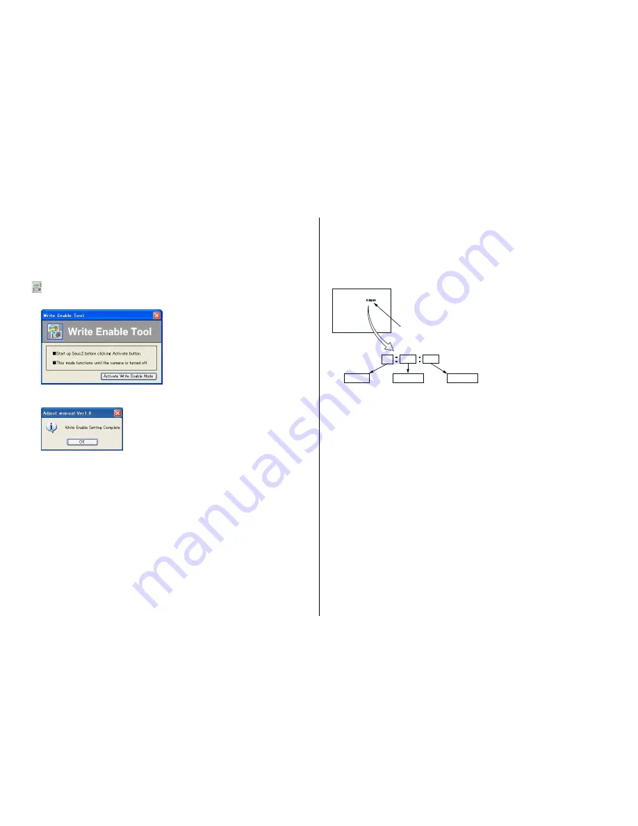
設定の変更は,Adjust StationからAdjust Manualを起動させて書き込み許可ツール(Write Enable Tool)を使用します。

書き戻し方法 

1)  Adjust StationからAdjust Manualを起動する。

2) 

 (Write Enable Tool)ボタンをクリックする。

3)  “Activate Write Enable Mode”ボタンをクリックする。

4)


設定の変更が終了すると,次のメッセージが表示されますので“OK”ボタンをクリックする。

5)  ドライバを元に戻して、カメラとPCをマスストレージ接続する。
 

Write Enable Tool使用時、手順 5) では以下の作業を行なってください。


1.  USBケーブルをカメラから抜く。


2.  調整設定用メモリースティックを抜く。


3.  メモリースティック(調整設定用メモリースティックで無いもの)を挿入し、取り外す。


4.  USBケーブルを接続する。これによってMass Storageモードで接続される。

6)  PCに読み出しておいたデータをカメラの内蔵メモリに書き込む。
7)  カメラとPCの接続を解除し,カメラの電源をOFFにする。

注意:

 カメラの電源をOFFにすることにより,書き込み許可の設定が解除されます。

1-4.  修理時の電源供給について

本機ではバッテリー(NP-BN1)を使用してください。
外部からの電源供給はできません。

1-5.  自己診断機能

1-5-1. 自己診断機能について

本機の動作に不具合が生じたとき,自己診断機能が働き,LCD
画面に,どう処置したらよいか判断できる表示を行います。自
己診断機能については取扱説明書にも掲載されて
います。

1-5-2. 自己診断表示

本機の動作に不具合が生じたとき,LCD画面にアルファベッ
トと4桁の数字が表示され,3.2Hzで点滅します。この5文字の
表示によって対応者分類および不具合の生じたブロックの分
類,不具合の詳細コードを示します。

0 0

C

3 2

対応者分類 

「1‑5‑3. 自己診断コード表」を参照 

対応方法の違いにより分類 

13・・・ メモリーカード を

フォーマットする 

32・・・電源を入れ直す 

ブロック分類 

詳細コード 

3.2 Hz点滅 

C:お客さま自身で対応 


E:サービスエンジニア


で対応 

LCD画面 

0 0

C

3 2

対応者分類 

「1‑5‑3. 自己診断コード表」を参照 

対応方法の違いにより分類 

13・・・ メモリーカード を

フォーマットする 

32・・・電源を入れ直す 

ブロック分類 

詳細コード 

3.2 Hz点滅 

C:お客さま自身で対応 


E:サービスエンジニア


で対応 

LCD画面 

Содержание Cybershot,Cyber-shot DSC-W530

Страница 1: ... 9 834 542 31 DSC W530 Ver Date History Contents S M Rev issued 1 0 2010 11 Official Release 2010K08 1 2010 11 ENGLISH 1 1 PRECAUTION ON REPLACING THE SY 285 BOARD 1 2 METHOD FOR COPYING OR ERASING THE DATA IN INTERNAL MEMORY 1 3 HOW TO WRITE DATA TO INTERNAL MEMORY 1 4 POWER SUPPLY ON REPAIRING 1 5 SELF DIAGNOSIS FUNCTION 1 6 PROCESS AFTER FIXING FLASH ERROR 1 7 Dedicated A V cable optional acces...

Страница 2: ... Speaker Monaural Exif Print Compatible PRINT Image Matching III Compatible BC CSN BC CSNB battery charger Power requirements AC 100 V to 240 V 50 60 Hz 2 W Output voltage DC 4 2 V 0 25 A Operating temperature 0 C to 40 C 32 F to 104 F Storage temperature 20 C to 60 C 4 F to 140 F Dimensions Approx 55mm 24mm 83mm 2 1 4inches 31 32inches 3 3 8inches W H D Mass Approx 55 g 1 9 oz Rechargeable batter...

Страница 3: ...nductor when soldering or unsoldering 1 注意事項をお守りください サービスのとき特に注意を要する個所については キャビ ネット シャーシ 部品などにラベルや捺印で注意事項を 表示しています これらの注意書き及び取扱説明書等の注 意事項を必ずお守り下さい 2 指定部品のご使用を セットの部品は難燃性や耐電圧など安全上の特性を持った ものとなっています 従って交換部品は 使用されていた ものと同じ特性の部品を使用して下さい 特に回路図 部 品表に0印で指定されている安全上重要な部品は必ず指定 のものをご使用下さい 3 部品の取付けや配線の引きまわしはもとどおりに 安全上 チューブやテープなどの絶縁材料を使用したり プリント基板から浮かして取付けた部品があります また 内部配線は引きまわしやクランパによって発熱部品や高圧 部品に接近しないよう配慮されていま...

Страница 4: ...n internal memory of the board before replacement Note 2 When replacing the SY 285 board execute formatting and initialize the internal memory after replacement Method for Copying the Data in Internal Memory Copy Copies all images in the internal memory to a memory card 1 Insert a memory card with sufficient free capacity into the camera 2 MENU Settings Memory Card Tool Copy OK Notes Use a fully c...

Страница 5: ... the PC to the internal memory of the camera 7 Disconnect the PC from the camera and turn off the camera Note By turning off the camera the write enable setting is reset 1 4 POWER SUPPLY ON REPAIRING Use the battery NP BN1 on repairing The external battery source cannot be used on repairing 1 5 SELF DIAGNOSIS FUNCTION 1 5 1 Self diagnosis Function When problems occur while the unit is operating th...

Страница 6: ...nosis Code Symptom State Correction Repaired by Block Function Detailed Code C 1 3 0 1 The internal memory has experienced a me dia error Turn the power off and on again The internal memory has experienced a for mat error Format the internal memory Memory card is unformatted Format the memory card Memory card is broken Insert a new memory card Memory card type error Insert a supported memory card ...

Страница 7: ...画面の操作から実行可能です 消去する場合は内蔵メモリーの初期化を行います Note1 SY 285基板交換の際は 基板交換前に内蔵メモリーのデータを消去して下さい Note2 SY 285基板交換の際は 基板交換後に内蔵メモリーのフォーマットおよび初期化を実行して下さい 内蔵メモリーのコピー方法 আ ش ওঔজ ش प ஈखञ ؚ ওঔজ ش ढ़ ॻش प ฐ আ ش खऽघ ౄীऩ૬ऌઍ भँॊওঔজ ش ढ़ ॻش মਃपোोॊ 0 18 ق ਝ ك ق ওঔজ ش ढ़ شॶॻش ঝ ك ن আ هش ن 2 ه র ఙभ ओିਔ ౄীपౄਗ਼खञংॵॸজ ش ओઞ ऎटऔः ଋ भ ऩःংॵॸজ ش ઞ खथ ই ॖঝ আ ش घॊध ؚ ংॵॸজ ش જोभञीॹ ॱش ૡଛदऌऩऊढञॉ ॱشॹؚ घ ॊउजोऋँॉऽघ ओधभ আ ش मदऌऽच ॹ ॱش আ ش खथु ؚ ওঔ...

Страница 8: ...挿入し 取り外す 4 USBケーブルを接続する これによってMass Storageモードで接続される 6 PCに読み出しておいたデータをカメラの内蔵メモリに書き込む 7 カメラとPCの接続を解除し カメラの電源をOFFにする 注意 カメラの電源をOFFにすることにより 書き込み許可の設定が解除されます 1 4 修理時の電源供給について 本機ではバッテリー NP BN1 を使用してください 外部からの電源供給はできません 1 5 自己診断機能 1 5 1 自己診断機能について 本機の動作に不具合が生じたとき 自己診断機能が働き LCD 画面に どう処置したらよいか判断できる表示を行います 自 己診断機能については取扱説明書にも掲載されて います 1 5 2 自己診断表示 本機の動作に不具合が生じたとき LCD画面にアルファベッ トと4桁の数字が表示され 3 2Hzで点滅します この5文字の...

Страница 9: ...れ直す 復帰しない場合はレンズブロックのフォーカスリセットセン サ SY 285基板CN401 qhピン を点検する 異常なければフォーカスモータ駆動IC SY 285基板IC401 を 点検する E 9 1 0 1 フラッシュの充電異常 フラッシュユニットを点検または交換する Note Note 交換後は 必ず 1 6 フラッシュエラー発生時の対処法 を行って下さい 1 6 フラッシュエラー発生時の対処法 本機はフラッシュエラー 自己診断コードE 91 01 が発生した場合 高電圧による異常を防止するために自動的にフラッシュ充 電および発光禁止の設定になります フラッシュエラー発生後はエラーの解除を行う必要があります エラーの解除はホーム画面から初期化操作を実行することにより行 います フラッシュエラーの解除方法 ਝ জ७ॵॺ उେः ऑৎभਝ पರखऽघ नठैभਝ জ७ॵॺ ৰষखथ...

Страница 10: ... tweezers or a needle shown below into a gap of Ornamental Ring A 4 Remove while turning the Ornamental Ring A right and left Solvent Ornamental Ring A Tweezers Barrier Assy Claws Claws Barrier Assy Claws Claws Barrier Lever Hole Removal 1 Remove four screws and removetheRearMirrorPlate 2 Remove one screw 3 Remove the four soldering and remove the Optical Stepping Motor F1380 1 Solder the four loc...

Страница 11: ...eRearMirrorPlate with the four screws in the order of numbers Tightening torque 0 049 0 01N m 0 5 0 1kgf cm Installation Screw Screw Screw Screw Rear Mirror Plate Naruto Gear Lubricated Assy Warm B Lubricated Assy 4 1 2 3 Screw Screw Screw FG Seal Screw Screw Screw Rear Mirror Plate Naruto Gear Lubricated Assy Warm B Lubricated Assy Solders DC Motor Worm A Assy Screw Screw FG Seal Solders DC Motor...

Страница 12: ...d Assy and align the two points of ditches of the Straight Tube Lubricated Assy with ditchies of the Cam Tube Block Assy then remove the Straight Tube Lubricated Assy from the Cam Tube BlockAssy qf Pour a solvent such as alcohol from two places qg Remove while turning the Ornamental Ring A right and left qh Remove Barrier Assy by disengaging four claws qj Remove the bond at the three points qk Rot...

Страница 13: ...Barrier Assy Claws Claws Ornamental Ring A Barrier Lever Hole 8 Install the Straight Tube Lubricated to the Cam Tube Block Assy 9 Rotate about 120 degree Straight Tube Lubricated Assy and align two points of ditches of the Straight Tube Lubricated Assy with ditches of the Cam Tube BlockAssy q Match three ledges of the 1 Group Assy to three ditches of the Cam Tube Block Assy and install it qa Match...

Страница 14: ... Stationary Tube Block Fixed Stationary Tube Block Ditches Convex Parts Flexible Board Fixed Stationary Tube Naruto Gear Naruto Gear Lubricated Assy qj Install the Warm B Lubricated Assy qk Connect the Iris Flexible Board from connector of 2 Frame Assy w Install the 3 Group Frame ql Install the 3 Group Spring wa Install theRearMirrorPlate with the four screws in the order of numbers Tightening tor...

Страница 15: ... Memory card PC 2 Shoot setting 1 Paste the chart Chart should be on the flat wall Illuminance level in the chart should be the same Make the tripod s height and the center of the chart to the same height Enough space needed for shooting 2 Set the camera Set P mode Set Maximum size Set ISO lowest level Set Steady Shot OFF Set Flash OFF 3 Set the camera on a tripod 4 Adjust the position of the came...

Страница 16: ...ilm resistor METAL OXIDE Metal Oxide film resistor F nonflammable SEMICONDUCTORS In each case u μ for example uA μA uPA μPA uPB μPB μPC μPC uPD μPD The components identified by mark 0 or dotted line with mark 0 are critical for safety Replace only with part number specified Les composants identifiés par une marque 0 sont critiques pour la sécurité Ne les remplacer que par une pièce portant le numé...

Страница 17: ...ischarged as described below Preparing the Short Jig To preparing the short jig a small clip is attached to each end of a resistor of 1 kΩ 1 W 1 215 869 11 Wrap insulating tape fully around the leads of the resistor to prevent elec trical shock 1 kΩ 1 W Wrap insulating tape 1 kΩ 1 W Wrap insulating tape MA 473 Flexible Board R 1 k Ω 1 W C901 Note High voltage cautions Discharging the Capacitor Sho...

Страница 18: ...765 01 SCREW M1 4 NEW TRU STAR P2 Note 1 1 Remove to numerical order 1 to 6 in the left figure DISASSEMBLY 1 209 210 X 5 Screw 1 8 Note 3 6 LCD901 3 Note 2 2 Note 2 4 5 209 210 Note 1 209 210 Note 1 209 210 Note 1 Front Top Section See page 2 4 4 7 5 6 2 9 3 1 5 Claw 1 Claw 209 210 209 210 209 210 Bottom View Left View Right View Note Note 1 THE COMBINATION OF CABINET S COLOR AND SCREW The screw p...

Страница 19: ...01 SCREW M1 4 NEW TRU STAR P2 Note 1 1 Remove to numerical order 1 to 6 in the left figure DISASSEMBLY 1 209 210 X 1 Screw 209 210 Note 1 C901 BT900 5 55 53 54 Note 3 BT900 LITHIUM RECHARGEABLE BATTERY Board on the mount position See page 6 20 of Level3 Main Section See page 2 5 2 51 1 66 SP901 Note 3 6 57 Note 3 MIC901 Note 3 56 2 Claw 67 58 60 61 4 3 64 4 2 4 1 63 365 4 62 5 59 3 Claws 4 Claw 20...

Страница 20: ...ERY Note 3 BT903 1 780 835 11 TERMINAL BOARD BATTERY Note 3 1 Remove to numerical order 1 to 4 in the left figure 2 The meaning of the sign in left figure is as follows Be careful when it removes X Solder DISASSEMBLY 3 106 BT902 Note 3 BT903 Note 3 BT901 Note 3 1 Lens Block Section See page 2 6 Note 1 107 Note 2 4 101 2 104 102 103 105 102 102 3 Note Note 2 Refer to Assembly 2 Insulating Sheet 670...

Страница 21: ...ing each item when you exchange parts of Lens Block 1 8 ORNAMENTAL RING A OR BARRIER ASSY REPLACING METHOD page1 7 1 9 OPTICAL STEPPING MOTOR F1380 REPLACING METHOD page 1 7 1 10 DC MOTOR WORM A ASSY REPLACING METHOD page 1 8 1 11 CAM TUBE BLOCK ASSY and STRAIGHT TUBE LUBRICATED ASSY and 1 GROUP FRAME REPLACING METHOD page 1 8 1 12 FINAL INSPECTION page 1 12 Note 3 Be sure to read Precautions for ...

Страница 22: ...ttery pack NP BN1 Note1 Wrist strap 2 050 981 01 Gray SILVER PINK GREEN 2 050 981 11 Black BLACK BLUE Dedicated USB cable 1 834 311 51 Note1 This item is supplied with the unit as an accessory but is not prepared as a service part Note2 Dedicated A V cable optional accessory Dedicated A V cable is not supplied with this model If you need dedicated A V cable order 1 834 312 4 or VMC 15CSR1 CD ROM C...

Страница 23: ...tion During of MA 473 Flexible Board Installation Route the speaker harness and microphone harness as shown below Speaker Harness Tape SP Microphone Harness MA 473 Flexible Board Microphone Harness MA 473 Flexible Board Assembly 4 Precaution During of Cabinet Rear Assy Installation Align the slide switch at the camera mode when install cabinet rear assy Slide Switch Cabinet Rear Assy Assembly 5 At...

Отзывы: