— 9 —
SECTION 4
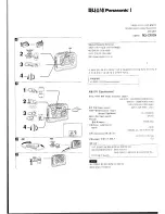
DIAL POINTER INSTALLATION
Note :
Follow the installation procedure in the numerical order given.
1
Align the pointer with the groove of front cabinet assy and insert it as shown in the illustration.
2
Align Knob (TU) with front cabinet and fasten the screw.
3
Turn the Knob (TU) in the direction of the arrow as shown in the illustration until pointer agrees with scale “ 0 ” (at leftmost end of
scale).
4
Turn the tuning capacitor gear fully in the direction of the arrow as shown in the illustration.
5
Fasten the front cabinet assy and rear cabinet assy with the screws.
2
Screw
+BVTP 2.6
×
8
1
Pointer
Knob (TU)
Front Cabinet assy
3
Knob (TU)
4
Tuning capacitor gear
Rear cabinet assy
5


