


4
CDX-S1000/S2000/S2000C
TABLE OF CONTENTS
1. GENERAL
Location of controls ................................................................. 5
Connections ............................................................................. 6
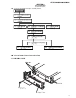
2. DISASSEMBLY
2-1. Sub Panel (1) Assy .............................................................. 7
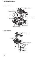
2-2. CD Mechanism Block ......................................................... 8
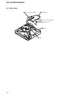
2-3. Main Board ......................................................................... 8
2-4. Chassis (T) Sub Assy .......................................................... 9
2-5. Roller Arm Assy .................................................................. 9
2-6. Chassis (OP) Assy ............................................................. 10
2-7. Optical Pick-up ................................................................. 10
2-8. SL Motor Assy (M902) ..................................................... 11
2-9. LE Motor Assy (M903) ..................................................... 11
2-10. Servo Board ....................................................................... 12
3. DIAGRAMS
3-1. IC Pin Descriptions ........................................................... 13
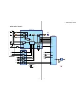
3-2. Block Diagram –CD Section– ........................................... 17
3-3. Block Diagram –Tuner Section– ....................................... 18
3-4. Block Diagram –Display Section– .................................... 19
3-5. Printed Wiring Boards –CD Mechanism Section– ............ 21
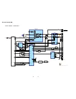
3-6. Schematic Diagram –CD Mechanism Section– ................ 22
3-7. Printed Wiring Board –Main Section– .............................. 23
3-8. Schematic Diagram –Main Section (1/2)– ........................ 24
3-9. Schematic Diagram –Main Section (2/2)– ........................ 25
3-10. Printed Wiring Board –Key Section– ................................ 26
3-11. Schematic Diagram –Key Section– ................................... 27
3-12. IC Block Diagrams ............................................................ 28
4. EXPLODED VIEWS
4-1. Main Section ..................................................................... 30
4-2. Front Panel Section ........................................................... 31
4-3. CD Mechanism Section (1) ............................................... 32
4-4. CD Mechanism Section (2) ............................................... 33
4-5. CD Mechanism Section (3) ............................................... 34
4-6. CD Mechanism Section (4) ............................................... 35
5. ELECTRICAL PARTS LIST
........................................ 36
Содержание CDX-S1000
Страница 6: ...6 CDX S1000 S2000 S2000C Connections ...


