background image

8

CDX-GT42IPW/GT44IP/GT420IP

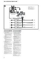
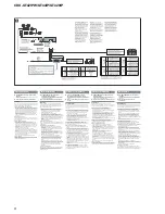
L

R

REAR

FRONT

BUS

AUDIO OUT

IN

AUDIO OUT REAR

*

3

5

7

4

8

1

3

5

7

2

4

6

8

*

1

 from car antenna (aerial)


von Autoantenne


de l’antenne de la voiture


dall’antenna dell’auto


van een auto-antenne

Fuse (10 A)
Sicherung (10 A)
Fusible (10 A)
Fusibile (10 A)
Zekering (10 A)

AMP REM

Light blue
Hellblau
Bleu ciel
Azzurro
Lichtblauw

Blue/white striped
Blauweiß gestreift
Rayé bleu/blanc
Rigato blu e bianco
Blauw/wit gestreept

from the car’s power connector
vom Stromanschluss des Fahrzeugs
du connecteur d’alimentation de la voiture
dal connettore di alimentazione dell’auto
van de autovoedingsaansluiting

ATT

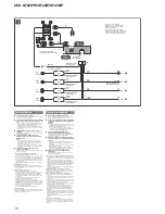
See “Power connection diagram” on the reverse side for details.

Näheres dazu fi nden Sie im „Stromanschlussdiagramm“. Blättern 
Sie dazu bitte um.

Voir le « Schéma de raccordement d’alimentation » au verso pour 
plus de détails.

Per ulteriori informazioni, vedere “Diagramma dei collegamenti di 
alimentazione” che si trova sul retro.

Zie "Voedingsaansluitschema" op de achterkant voor meer details.

*

1

  Note for the antenna (aerial) connecting

If your car antenna (aerial) is an 
ISO (International Organization for 
Standardization) type, use the supplied 
adaptor 

2

 to connect it. First connect 

the car antenna (aerial) to the supplied 
adaptor, then connect it to the antenna 
(aerial) jack of the master unit.

*

2

  RCA pin cord (not supplied)

*

AUDIO OUT can be switched SUB or 
REAR. For details, see the supplied 
Operating Instructions.

*

1

  Hinweis zum Anschließen der Antenne

Wenn Ihre Autoantenne der ISO-Norm 
(Internationale Normungsgemeinschaft) 
entspricht, schließen Sie sie mithilfe des 
mitgelieferten Adapters 

2

 an. Verbinden 

Sie zuerst die Autoantenne mit dem 
mitgelieferten Adapter und verbinden Sie 
diesen dann mit der Antennenbuchse 
des Hauptgeräts.

*

2

  Cinchkabel (nicht mitgeliefert)

*

3

  AUDIO OUT kann zwischen SUB 

und REAR umgeschaltet werden. 
Näheres hierzu fi nden Sie in der 
Bedienungsanleitung.

*

1

  Remarque sur le raccordement de 

l’antenne
Si votre antenne de voiture est de type 
ISO (Organisation internationale de 
normalisation), utilisez l’adaptateur fourni 

 pour la raccorder. Raccordez d’abord 

l’antenne de voiture à l’adaptateur fourni 
et, ensuite, à la prise d’antenne de 
l’appareil principal.

*

2

  Cordon à broche RCA (non fourni)

*

AUDIO OUT peut être commuté sur SUB 
ou REAR. Pour obtenir plus de détails, 
reportez-vous au mode d’emploi.

*

1

  Nota per il collegamento dell’antenna

Se l’antenna dell’auto è di tipo 
ISO (International Organization for 
Standardization), utilizzare l’adattatore 

 in dotazione per collegar

2

2

la. Collegare 

prima l’antenna della macchina 
all’adattatore in dotazione, quindi 
collegarla alla presa dell’antenna 
dell’apparecchio principale.

*

2

  Cavo a piedini RCA (non in dotazione)

*

AUDIO OUT può essere impostato 
su SUB o su REAR. Per ulteriori 
informazioni, consultare il manuale di 
istruzioni per l’uso.

*

1

  Opmerking bij de antenne-aansluiting

Indien uw auto is uitgerust met een 
antenne van het type ISO (International 
Organization for Standardization), 
moet u die aansluiten met behulp 
van de bijgeleverde adapter 

2

. Sluit 

eerst de auto-antenne aan op de 
bijgeleverde adapter en vervolgens de 
antennestekker op het hoofdtoestel.

*

2

  Tulpstekkersnoer (niet bijgeleverd)

*

AUDIO OUT kan worden ingesteld 
op SUB of REAR. Raadpleeg de 
gebruiksaanwijzing voor meer informatie.

Max. supply current 0.3 A
max. Versorgungsstrom 0,3 A
Courant d’alimentation maximum 0,3 A
Alimentazione massima fornita 0,3 A
Max. voedingsstroom 0,3 A

Negative polarity positions 2, 4, 6, and 8 have striped leads.
An den negativ gepolten Positionen 2, 4, 6 und 8 befi nden sich gestreifte Adern.
Les positions de polarité négative 2, 4, 6 et 8 sont dotées de cordons rayés.
Le posizioni a polarità negativa 2, 4, 6 e 8 hanno cavi rigati.
De posities voor negatieve polariteit (2, 4, 6 en 8) hebben gestreepte kabels.

1

Purple
Violett

Violet

Viola

Paars

+

Speaker, Rear, Right

Lautsprecher hinten rechts

Haut-parleur, arrière, droit

Diffusore, posteriore, destro

Luidspreker, achter, rechts

5

White

Weiß

Blanc

Bianco

Wit

+

Speaker, Front, Left

Lautsprecher vorne links

Haut-parleur, avant, gauche

Diffusore, anteriore, sinistro

Luidspreker, voor, links

2

Speaker, Rear, Right

Lautsprecher hinten rechts

Haut-parleur, arrière, droit

Diffusore, posteriore, destro

Luidspreker, achter, rechts

6

Speaker, Front, Left

Lautsprecher vorne links

Haut-parleur, avant, gauche

Diffusore, anteriore, sinistro

Luidspreker, voor, links

3

Gray
Grau

Gris

Grigio

Grijs

+

Speaker, Front, Right

Lautsprecher vorne rechts

Haut-parleur, avant, droit

Diffusore, anteriore, destro

Luidspreker, voor, rechts

7

Green

Grün

Vert

Verde

Groen

+

Speaker, Rear, Left

Lautsprecher hinten links

Haut-parleur, arrière, gauche

Diffusore, posteriore, sinistro

Luidspreker, achter, links

4

Speaker, Front, Right

Lautsprecher vorne rechts

Haut-parleur, avant, droit

Diffusore, anteriore, destro

Luidspreker, voor, rechts

8

Speaker, Rear, Left

Lautsprecher hinten links

Haut-parleur, arriè re, gauche

Diffusore, posteriore, sinistro

Luidspreker, achter, links

*

2

from the car’s speaker connector
vom Lautsprecheranschluss des Fahrzeugs
du connecteur de haut-parleur de la voiture
dal connettore dei diffusori dell’auto
van de autoluidsprekeraansluiting

Positions 1, 2, 3, and 6 do not have pins.
An Position 1, 2, 3 und 6 befi nden sich keine Stifte.
Les positions 1, 2, 3 et 6 ne comportent pas de broches.
Le posizioni 1, 2, 3 e 6 non hanno piedini.
De posities 1, 2, 3 en 6 hebben geen pins.

4

Yellow

Gelb

Jaune
Giallo

Geel

continuous power supply

permanente Stromversorgung

alimentation continue

alimentazione continua

continu voeding

7

Red

Rot

Rouge
Rosso

Rood

switched power supply

geschaltete Stromversorgung

alimentation commutée

alimentazione commutata

geschakelde voeding

5

Blue
Blau
Bleu

Blu

Blauw

power antenna (aerial) control

Motorantennensteuerung

antenne électrique

comando dell’antenna elettrica

elektrische antenne

8

Black

Schwarz

Noir

Nero

Zwart

ground (earth)

Masse
masse

terra

aarding

2

3

Aansluitschema  

A

Naar AMP REMOTE IN van een optionele 
versterker

Deze aansluiting is alleen bedoeld voor versterkers. Door 
een ander systeem aan te sluiten kan het apparaat worden 
beschadigd.

B

Naar het interface-snoer van een 
autotelefoon

Waarschuwing

Indien u een elektrische antenne hebt zonder relaiskast, 
kan het aansluiten van dit apparaat met de bijgeleverde 
voedingskabel 

3

 de antenne beschadigen.

Opmerkingen over de bedienings- en voedingskabels
• De bedieningskabel van de elektrische antenne (blauw) levert 

+12 V gelijkstroom wanneer u de tuner inschakelt of de AF 
(alternatieve frequenties) of TA (verkeersinformatie) functie 
activeert.

• Wanneer uw auto is uitgerust met een FM/MW/LW-antenne 

in de achterruit/zijruit, moet u de bedieningskabel van de 
elektrische antenne (blauw) of de voedingskabel van de 
accessoires (rood) aansluiten op de voedingsingang van de 
bestaande antenneversterker. Raadpleeg uw dealer voor meer 
details.

• Met dit apparaat is het niet mogelijk een elektrische antenne 

zonder relaiskast te gebruiken.

Instandhouden van het geheugen
Zolang de gele voedingskabel is aangesloten, blijft de 
stroomvoorziening van het geheugen intact, ook wanneer de 
contactschakelaar van de auto wordt uitgeschakeld.

Opmerkingen betreffende het aansluiten van de luidsprekers
• Zorg dat het apparaat is uitgeschakeld, alvorens de 

luidsprekers aan te sluiten.

• Gebruik luidsprekers met een impedantie van 4 tot 8 Ohm 

en let op dat die het vermogen van de versterker kunnen 
verwerken. Als u dit niet doet, kunnen de luidsprekers ernstig 
beschadigd raken.

• Verbind in geen geval de aardingskabel van de luidsprekers 

met het chassis van de auto en sluit de aansluitingen van de 
rechter- en linkerluidspreker niet op elkaar aan.

• Verbind de aarddraad van dit apparaat niet met de negatieve 

(–) aansluiting van de luidspreker.

• Probeer nooit de luidsprekers parallel aan te sluiten.
• Sluit geen actieve luidsprekers (met ingebouwde versterkers) 

aan op de luidsprekeraansluiting van dit apparaat. Dit zal 
leiden tot beschadiging van de actieve luidsprekers. Sluit dus 
altijd uitsluitend luidsprekers zonder ingebouwde versterker 
aan.

• Om defecten te vermijden mag u de bestaande 

luidsprekerbedrading in uw auto niet gebruiken wanneer er een 
gemeenschappelijke negatieve (–) kabel is voor de rechter- en 
linkerluidsprekers.

• Verbind de luidsprekerkabels niet met elkaar.

Opmerking over aansluiten
Als de luidspreker en versterker niet goed zijn aangesloten, 
wordt "FAILURE" in het display weergegeven. In dit geval moet u 
zorgen dat de luidspreker en versterker correct zijn aangesloten.

Schémas de raccordement  

A

Au niveau du AMP REMOTE IN d’un 
amplifi cateur de puissance facultatif

Ce raccordement existe seulement pour les amplifi cateurs. 
Le raccordement à tout autre système peut endommager 
l’appareil.

B

Vers le cordon de liaison d’un téléphone de 
voiture

Avertissement

Si vous disposez d’une antenne électrique sans boîtier 
de relais, le branchement de cet appareil au moyen du 
cordon d’alimentation fourni 

3

 risque d’endommager 

l’antenne.

Remarques sur les câbles de commande et d’alimentation

Le câble de commande (bleu) fournit du courant continu de 
+12 V lorsque vous mettez le tuner sous tension ou lorsque 
vous activez la fonction AF (fréquence alternative) ou TA 
(messages de radioguidage).

Lorsque votre voiture est équipée d’une antenne FM/MW 
(GO)/LW (PO) intégrée dans la vitre arrière/latérale, 
raccordez le câble de commande d’antenne (bleu) ou le 
câble d’alimentation des accessoires (rouge) à la borne 
d’alimentation de l’amplifi cateur d’antenne existant. Pour plus 
de détails, consultez votre revendeur.

Une antenne électrique sans boîtier de relais ne peut pas être 
utilisée avec cet appareil.

Raccordement pour la conservation de la mémoire
Lorsque le câble d’alimentation jaune est connecté, le circuit 
de la mémoire est alimenté en permanence même si la clé de 
contact est en position d’arrêt.

Remarques sur le raccordement des haut-parleurs

Avant de raccorder les haut-parleurs, mettez l’appareil hors 
tension.

Utilisez des haut-parleurs ayant une impédance de 4 à 8 ohms 
et une capacité adéquate sous peine de les endommager.

Ne raccordez pas les bornes du système de haut-parleurs au 
châssis de la voiture et ne pas connecter les bornes du haut-
parleur droit à celles du haut-parleur gauche.

Ne raccordez pas le câble de mise à la masse de cet appareil 
à la borne négative (–) du haut-parleur.

• Ne tentez pas de raccorder les haut-parleurs en parallèle.
• Connectez uniquement des haut-parleurs passifs. Le 

raccordement de haut-parleurs actifs (avec des amplifi cateurs 
intégrés) aux bornes des haut-parleurs pourrait endommager 
l’appareil.

Pour éviter tout problème de fonctionnement, n’utilisez pas les 
câbles des haut-parleurs intégrés installés dans votre voiture 
si l’appareil dispose d’un câble négatif commun (–) pour les 
haut-parleurs droit et gauche.

Ne raccordez pas entre eux les cordons des haut-parleurs de 
l’appareil.

Remarque sur le raccordement
Si les haut-parleurs et l’amplifi cateur ne sont pas raccordés 
correctement, le message « FAILURE » s’affi che. Dans ce 
cas, assurez-vous que les haut-parleurs et l’amplifi cateur sont 
raccordés correctement.

Anschlussdiagramm  

A

An AMP REMOTE IN des gesondert 
erhältlichen Endverstärkers

Dieser Anschluss ist ausschließlich für Verstärker gedacht. 
Schließen Sie nichts anderes daran an. Andernfalls kann 
das Gerät beschädigt werden.

B

An Schnittstellenkabel eines Autotelefons

Warnung

Wenn Sie eine Motorantenne ohne Relaiskästchen 
verwenden, kann durch Anschließen dieses Geräts mit 
dem mitgelieferten Stromversorgungskabel 

3

 die 

Antenne beschädigt werden.

Hinweise zu den Steuer- und Stromversorgungsleitungen

Die Motorantennen-Steuerleitung (blau) liefert  +12 V 
Gleichstrom, wenn Sie den Tuner einschalten oder die 
AF- (Alternativfrequenzsuche) oder die TA-Funktion 
(Verkehrsdurchsagen) aktivieren.

Wenn das Fahrzeug mit einer in der Heck-/
Seitenfensterscheibe integrierten FM (UKW)/MW/LW-
Antenne ausgestattet ist, schließen Sie die Motorantennen-
Steuerleitung (blau) oder die Zubehörstromversorgungsleitung 
(rot) an den Stromversorgungsanschluss des vorhandenen 
Antennenverstärkers an. Näheres dazu erfahren Sie bei Ihrem 
Händler.

Es kann nur eine Motorantenne mit Relaiskästchen 
angeschlossen werden.

Stromversorgung des Speichers
Wenn die gelbe Stromversorgungsleitung angeschlossen ist, 
wird der Speicher stets (auch bei ausgeschalteter Zündung) mit 
Strom versorgt.

Hinweise zum Lautsprecheranschluss

Schalten Sie das Gerät aus, bevor Sie die Lautsprecher 
anschließen.

Verwenden Sie Lautsprecher mit einer Impedanz zwischen 4 und 
8 Ohm und ausreichender Belastbarkeit. Ansonsten können die 
Lautsprecher beschädigt werden.

Verbinden Sie die Lautsprecheranschlüsse nicht mit dem 
Wagenchassis und verbinden Sie auch nicht die Anschlüsse 
des rechten mit denen des linken Lautsprechers.

Verbinden Sie die Masseleitung dieses Geräts nicht mit dem 
negativen (–) Lautsprecheranschluss.

Versuchen Sie nicht, Lautsprecher parallel anzuschließen.

An die Lautsprecheranschlüsse dieses Geräts dürfen nur 
Passivlautsprecher angeschlossen werden. Schließen Sie 
keine Aktivlautsprecher (Lautsprecher mit eingebauten 
Verstärkern) an, da das Gerät sonst beschädigt werden 
könnte.

Um Fehlfunktionen zu vermeiden, verwenden Sie nicht die 
im Fahrzeug installierten, integrierten Lautsprecherleitungen, 
wenn am Ende eine gemeinsame negative (–) Leitung für den 
rechten und den linken Lautsprecher verwendet wird.

Verbinden Sie nicht die Lautsprecherkabel des Geräts 
miteinander.

Hinweis zum Anschließen
Wenn Lautsprecher und Verstärker nicht richtig angeschlossen 
sind, erscheint „FAILURE“ im Display. Vergewissern Sie sich 
in diesem Fall, dass Lautsprecher und Verstärker richtig 
angeschlossen sind.

Schema di collegamento  

A

A AMP REMOTE IN di un amplifi catore di 
potenza opzionale 

Questo collegamento è riservato esclusivamente agli 
amplifi catori. Non collegare un tipo di sistema diverso onde 
evitare di causare danni all’apparecchio.

B

Al cavo di interfaccia di un telefono per auto

Avvertenza

Quando si collega l’apparecchio con il cavo di 
alimentazione in dotazione 

3

, si potrebbe danneggiare 

l’antenna elettrica se questa non dispone di scatola a relè.

Note sui cavi di controllo e di alimentazione

Il cavo (blu) di controllo dell’antenna elettrica fornisce 
alimentazione pari a +12 V CC quando si attiva il 
sintonizzatore oppure la funzione TA (notiziario sul traffi co) o 
AF (frequenza alternativa).

Se l’automobile è dotata di antenna FM/MW/LW incorporata 
nel vetro posteriore/laterale, collegare il cavo (blu) di 
controllo dell’antenna elettrica o il cavo (rosso) di ingresso 
dell’alimentazione ausiliaria al terminale di alimentazione 
dell’amplifi catore di potenza dell’antenna esistente. Per ulteriori 
informazioni, consultare il proprio fornitore.

Non è possibile usare un’antenna elettrica senza scatola a relè 
con questo apparecchio.

Collegamento per la conservazione della memoria
Quando il cavo di alimentazione giallo è collegato, viene sempre 
fornita alimentazione al circuito di memoria anche quando 
l’interruttore di accensione è spento.

Note sul collegamento dei diffusori

Prima di collegare i diffusori spegnere l’apparecchio.

Usare diffusori di impedenza compresa tra 4 e 8 ohm e con 
capacità di potenza adeguata, altrimenti i diffusori potrebbero 
venire danneggiati.

Non collegare i terminali del sistema diffusori al telaio dell’auto 
e non collegare i terminali del diffusore destro a quelli del 
diffusore sinistro. 

Non collegare il cavo di terra di questo apparecchio al 
terminale negativo (–) del diffusore.

Non collegare i diffusori in parallelo.

Assicurarsi di collegare soltanto diffusori passivi, poiché 
il collegamento di diffusori attivi, dotati di amplifi catori 
incorporati, ai terminali dei diffusori potrebbe danneggiare 
l’apparecchio.

Per evitare problemi di funzionamento, non utilizzare i cavi dei 
diffusori incorporati installati nell’automobile se l’apparecchio 
condivide un cavo comune negativo (–) per i diffusori destro e 
sinistro.

Non collegare fra loro i cavi dei diffusori dell’apparecchio.

Nota sui collegamenti
Se l’amplifi catore e il diffusore non sono collegati correttamente, 
“FAILURE” viene visualizzato nel display. In tal caso, accertarsi 
che l’amplifi catore e il diffusore siano collegati correttamente.

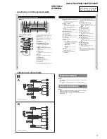
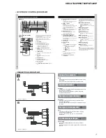
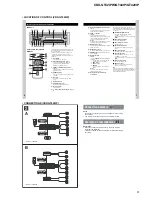
Connection diagram  

A

To AMP REMOTE IN of an optional power 
amplifi er

This connection is only for amplifi ers. Connecting any other 
system may damage the unit.

B

To the interface cable of a car telephone

Warning

If you have a power antenna (aerial) without a relay box, 
connecting this unit with the supplied power connecting 
lead 

3

 may damage the antenna (aerial).

Notes on the control and power supply leads

The power antenna (aerial) control lead (blue) su12 V 
DC when you turn on the tuner, or when you activate the AF 
(Alternative Frequency) or TA (Traffi c Announcement) function.

When your car has built-in FM/MW/LW antenna (aerial) in the 
rear/side glass, connect the power antenna (aerial) control 
lead (blue) or the accessory power supply lead (red) to the 
power terminal of the existing antenna (aerial) booster. For 
details, consult your dealer.

A power antenna (aerial) without a relay box cannot be used 
with this unit.

Memory hold connection
When the yellow power supply lead is connected, power will 
always be supplied to the memory circuit even when the ignition 
switch is turned off.

Notes on speaker connection

Before connecting the speakers, turn the unit off.

Use speakers with an impedance of 4 to 8 ohms, and with 
adequate power handling capacities to avoid its damage.

Do not connect the speaker terminals to the car chassis, or 
connect the terminals of the right speakers with those of the 
left speaker.

Do not connect the ground (earth) lead of this unit to the 
negative (–) terminal of the speaker.

Do not attempt to connect the speakers in parallel.

Connect only passive speakers. Connecting active speakers 
(with built-in amplifi ers) to the speaker terminals may damage 
the unit.

To avoid a malfunction, do not use the built-in speaker leads 
installed in your car if the unit shares a common negative (–) 
lead for the right and left speakers.

Do not connect the unit’s speaker leads to each other.

Note on connection
If speaker and amplifi er are not connected correctly, “FAILURE” 
appears in the display. In this case, make sure the speaker and 
amplifi er are connected correctly.

Содержание CDX-GT420iP - Radio / CD

Страница 1: ... 15 000 Hz AM CDX GT42IPW GT420IP Tuning range 530 1 710 kHz Antenna terminal External antenna connector Intermediate frequency 10 7 MHz 450 kHz Sensitivity 30 µV MW LW CDX GT44IP Tuning range MW 531 1 602 kHz LW 153 279 kHz Antenna terminal External antenna connector Intermediate frequency 10 7 MHz 450 kHz Sensitivity MW 30 µV LW 40 µV The tuner and CD sections have no adjustments Model Name Usin...

Страница 2: ...ts or performance of procedures other than those specified herein may result in hazardous radiation exposure Power amplifier section Outputs Speaker outputs sure seal connectors Speaker impedance 4 8 ohms Maximum power output 52 W 4 at 4 ohms General Output Audio outputs terminal CDX GT42IPW GT420IP front sub rear switchable CDX GT44IP sub rear switchable Power antenna aerial relay control termina...

Страница 3: ...e disc CD DA MP3 WMA TABLE OF CONTENTS 1 SERVICE NOTE 4 2 GENERAL Location of Controls CDX GT42IPW 5 Connections CDX GT42IPW 5 Location of Controls CDX GT44IP 7 Connections CDX GT44IP 7 Location of Controls CDX GT420IP 9 Connections CDX GT420IP 9 3 DISASSEMBLY 3 1 Sub Panel Assy 12 3 2 CD Mechanism Block 12 3 3 Main Board 13 3 4 Servo Board 13 3 5 Chassis T Sub Assy 14 3 6 Roller Arm Assy 14 3 7 C...

Страница 4: ...O board CN2 with the extension cable Part No J 2502 076 1 NOTE FOR REPLACEMENT OF THE SERVO BOARD When repairing the complete SERVO board A 1201 631 A should be replaced since any parts in the SERVO board cannot be repaired NOTE FOR REPLACEMENT OF THE AUX JACK J901 To replace the AUX jack requires alignment 1 Insert the AUX jack into the KEY board 2 Place the KEY board on the front panel 3 Solder ...

Страница 5: ...dio band FM AM select the play mode of iPod M BTM button page 8 To start the BTM function press and hold N RESET button located behind the front panel page 4 O Number buttons CD PD 1 2 ALBUM during MP3 WMA playback To skip albums press skip albums continuously press and hold 3 REP page 8 4 SHUF page 8 6 PAUSE To pause playback To cancel press again Radio To receive stored stations press store stat...

Страница 6: ...oid a malfunction do not use the built in speaker leads installed in your car if the unit shares a common negative lead for the right and left speakers Do not connect the unit s speaker leads to each other Note on connection If speaker and amplifier are not connected correctly FAILURE appears in the display In this case make sure the speaker and amplifier are connected correctly Diagrama de conexi...

Страница 7: ...bums continuously press and hold 3 REP page 8 4 SHUF page 8 6 PAUSE To pause playback To cancel press again Radio To receive stored stations press store stations press and hold P Receptor for the card remote commander The following buttons on the card remote commander have also different buttons functions from the unit Remove the insulation film before use page 4 qj buttons To control CD radio PD ...

Страница 8: ... du courant continu de 12 V lorsque vous mettez le tuner sous tension ou lorsque vous activez la fonction AF fréquence alternative ou TA messages de radioguidage Lorsque votre voiture est équipée d une antenne FM MW GO LW PO intégrée dans la vitre arrière latérale raccordez le câble de commande d antenne bleu ou le câble d alimentation des accessoires rouge à la borne d alimentation de l amplifica...

Страница 9: ...lay mode of iPod M BTM button page 8 To start the BTM function press and hold N RESET button located behind the front panel page 4 O Number buttons CD PD 1 2 ALBUM during MP3 WMA playback To skip albums press skip albums continuously press and hold 3 REP page 8 4 SHUF page 8 6 PAUSE To pause playback To cancel press again Radio To receive stored stations press store stations press and hold P Recep...

Страница 10: ...rface of the car first Remarques sur les câbles de commande et d alimentation Le câble de commande d antenne électrique bleu fournit une alimentation de 12 V CC lorsque vous mettez la radio sous tension Lorsque votre voiture est équipée d une antenne FM AM intégrée dans la vitre arrière latérale raccordez le câble de commande d antenne bleu ou le câble d alimentation des accessoires rouge à la bor...

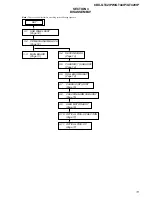
Страница 11: ...3 1 SUB PANEL ASSY Page 12 3 2 CD MECHANISM BLOCK Page 12 SET 3 3 MAIN BOARD Page 13 3 5 CHASSIS T SUB ASSY Page 14 3 6 ROLLER ARM ASSY Page 14 3 7 CHASSIS OP ASSY Page 15 3 8 CHUCKING ARM SUB ASSY Page 15 3 9 SLED MOTOR ASSY Page 16 3 10 OPTICAL PICK UP SECTION Page 17 3 11 OPTICAL PICK UP Page 17 3 4 SERVO BOARD Page 13 ...

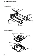
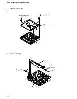
Страница 12: ... Note Follow the disassembly procedure in the numerical order given 3 1 SUB PANEL ASSY 2 two claws 3 two claws 4 sub panel assy 1 two screws PTT 2 6 6 4 CN350 3 1 screw PTT 2 6 6 2 screw PTT 2 6 6 5 two screws PTT 2 6 4 6 bracket CD 7 CD mechanism block ...

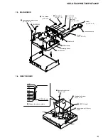
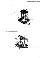
Страница 13: ...0 0 screw P 2 6 10 qs heat sink 8 two screws P 2 6 8 9 two screws PTT 2 6 10 1 three ground point screws PTT 2 6 6 7 connection cord 4 CN250 8P 5 CN200 3P 5 SERVO board SERVO board claw claw 3 toothed lock screw M 1 7 2 5 2 toothed lock screw M 1 7 2 5 1 Remove the eleven solders GRY YEL BLE ORG RED BLK RED WHT BLK RED WHT 4 optical pick up 16 core CN1 ...

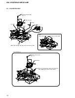
Страница 14: ... GT44IP GT420IP 3 6 ROLLER ARM ASSY 3 5 CHASSIS T SUB ASSY 4 chassis T sub assy 3 claw 1 two precision screws P 1 7 2 2 2 two precision screws P 1 7 2 2 3 washer 4 gear RA1 5 roller arm assy 1 spring RAL 2 spring RAR ...

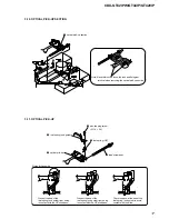
Страница 15: ...il spring damper black 6 chassis OP assy 5 1 tension spring KF 2 gear LE1 3 lever D 4 slider R 3 8 CHUCKING ARM SUB ASSY 3 chucking arm sub assy 2 1 spring Note Have this portion receive the chassis Note Have this portion receive the chassis Note Be careful not to touch the turn table ...

Страница 16: ... stand turn table 2 three serration screws M 2 3 three serration screws M 2 3 Note Place the stand with care not to touch the turn table Note Never remove these parts since they were adjusted Note for Assembly Note Take care to prevent the chassis from being bent when tightening the three machine screws ...

Страница 17: ...p section There is space at the end of the leaf spring sub guide to avoid contact with the slide 1 pan tapping screw M 1 4 2 5 2 leaf spring sub guide 3 leaf spring OP 5 optical pick up 4 lead screw assy Notes for Assembly Prevent the end of the leaf spring sub guide from being in contact with the OP slide base Prevent the end of the leaf spring sub guide from being in contact with the OP slide ba...

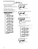
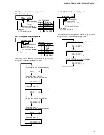
Страница 18: ... during the number of connected units display mode 4 4 Operating hours display mode Reset count display OFFSET FAILURE error display CD error information display Operating hours display Number of connected units display Reset count by watchdog timer display 0 1 X X 0 2 X X 0 3 1 X X X 0 4 X X X X 0 5 1 X X 0 6 1 X X X X X Reset count in hexadecimal format Diag code 01 Reset count 0 1 X X Reset cou...

Страница 19: ... error info history 3 Disc type plus operating hours display CD error info history 3 Error description plus error details display CD error info history 2 Disc type plus operating hours display CD error info history 2 Error description plus error details display CD error info history 1 latest Disc type plus operating hours display 0 5 1 X X X X X 0 5 2 X X 0 5 2 X X X X X 0 5 3 X X 0 5 3 X X X X X ...

Страница 20: ...20 CDX GT42IPW GT44IP GT420IP MEMO ...

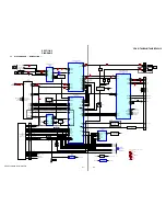
Страница 21: ... 6 VP2 30 AUDIO B 31 33 SERVO 3 3V MECHA 6V 34 PANEL B TU 5V 26 24 OUT FR OUT RR R CH R CH 21 22 SUBOUT L SUBOUT R 28 MUTE 4 SCL AUDIO 8 3V SERVO 3 3V MECHA 6V PANEL B 2 SDA 16 BEEP 22 STB 25 DIAG AUDIO 8 3V 7 10 12 11 16 1 9 2 4 3 6 29 30 SCL SDA 19 SAOUT 18 SADA 17 SACLK 15 SACLK 14 SAOUT 46 SAIN I2C SCL I2C SDA I2C SCL I2C SDA I2C SCL I2C SDA I2C SCL I2C SDA VSM QUALITY TUATT EEP SCL EEP SDA 8 ...

Страница 22: ... Parts face side Parts on the parts face side seen from the Side A parts face are indicated Q C These are omitted E B E These are omitted C B C These are omitted B E KEY ACKNOWLEDGE SWITCH Q664 X502 32 768kHz 79 80 40 28 29 27 41 52 76 SYSTEM CONTROL IC501 2 2 DISPLAY CONTROL IC901 KEYIN1 CL CE LCD_SO LCD_SCK LCD_CE 64 3 SIRCS OUT DIMMER KEYIN0 31 RE IN0 RE 0 RE 1 32 RE IN1 KEY ACK AD_ON XIN XOUT ...

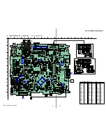
Страница 23: ...54 C318 R301 JC8 JC14 JC31 R450 R449 C432 C452 R447 R448 R421 R442 R471 R461 Q460 Q470 C434 R462 R472 C463 C462 C472 C473 JC11 JC9 C444 C424 R526 D503 D253 R294 L1 D260 JC253 R917 C210 C220 R233 R235 R222 R214 R212 JC211 JC217 JC212 R234 C207 C211 R213 Q210 JC210 JC512 JC511 JC213 JC214 C221 R220 R221 R211 R210 C152 C151 R154 R153 JC513 Q432 Q452 Q420 Q440 IC681 JC42 JC24 JC514 R517 R561 R509 R553...

Страница 24: ... C312 C320 C309 C307 C305 C330 C304 C302 C424 C444 C325 C301 C454 C434 D312 D311 D310 D309 D308 D307 D306 D305 D303 D304 C313 C316 C315 C314 L902 L901 JC31 C303 JC8 JC1 R606 R600 R531 C683 C682 C681 C624 C623 IC602 CN300 R705 D702 C704 C705 D704 D999 D998 R707 R702 R602 R601 JC32 JC33 JC12 JC508 JC511 Q701 Q702 Q605 F901 IC601 D491 IC300 R701 D607 L300 C701 5 4 SCHEMATIC DIAGRAM MAIN SECTION 1 4 R...

Страница 25: ...450 R12 R13 R15 Q1 L50 R430 R420 R460 R470 R440 R452 C461 C471 R471 R462 R472 C486 C485 R485 L1 JC9 JC11 L5 R481 JC50 JC210 JC212 JC513 R213 R211 R221 R222 R214 Q460 Q470 CN200 JC51 JC211 JC216 R233 R232 JC217 R212 JC13 JC10 JC15 C15 C426 C423 C445 C443 C442 C440 C452 C432 C463 C462 C472 C473 C484 C494 C493 R210 R220 C210 C220 C211 C207 C221 C231 C362 C361 C6 C7 C3 C8 C55 C60 C54 C11 C10 C58 JC6 J...

Страница 26: ...51 JC260 R293 JC992 JC262 JC261 JC256 JC254 R294 JC253 JC259 R290 JC990 JC991 IC260 C264 R291 CN250 C417 C415 C412 C402 C257 R273 C263 C268 C290 C291 C418 C419 C401 L407 JC34 JC35 JC258 JC257 R281 R280 R289 C266 C261 C260 C259 D252 D256 D253 C265 C258 Q256 CN350 L261 R282 R283 L291 L406 L410 5 6 SCHEMATIC DIAGRAM MAIN SECTION 3 4 Refer to page 34 for IC Block Diagrams Page 24 Page 25 Page 27 Page ...

Страница 27: ...917 D153 D113 JC100 JC101 JC102 JC214 JC504 JC512 JC255 C519 C507 C508 C510 C504 C916 C501 C513 C516 C515 R151 C154 C155 R152 R155 C152 JC213 R234 R235 R153 L151 C153 R154 C151 R671 C512 R522 R521 JC509 JC16 R505 JC23 C514 R524 R525 JC503 R567 R509 JC3 R636 JC18 JC40 R564 R507 R538 JC507 JC505 JC506 JC4 JC17 R519 R674 R568 C509 JC37 R553 R672 Q664 X501 C502 R673 S103 D502 JC2 D151 D152 D503 IC501 ...

Страница 28: ...es unleaded solder Page 23 1 A B C D E F G H 2 3 4 5 6 7 8 9 10 11 12 13 14 R253 R255 CN261 R254 R252 C250 R251 R250 D250 IC250 Q258 R288 R270 R292 1 12 C256 R268 R267 R266 R265 R264 R263 R261 R262 C255 C254 R260 R259 D255 R257 R256 C253 C251 C252 CN260 X250 1 874 161 11 11 1 874 161 11 11 A MAIN BOARD ...

Страница 29: ...RAM ATMEL SECTION Refer to page 22 for Waveforms Refer to page 35 for IC Block Diagrams Page 26 IC B D R256 R257 R259 R260 R261 R262 R263 R264 R265 R266 R267 R268 R288 R255 R253 R250 CN261 C253 C255 C256 CN260 R270 R292 R254 R252 X250 C252 C251 C250 R251 C254 Q258 D255 D250 IC250 ...

Страница 30: ...2 R911 R914 R952 R950 D991 D994 R951 IC901 R910 CN901 R971 Q931 R934 R942 R941 R992 R953 R954 R915 D903 J901 RE901 B MAIN BOARD CN370 OFF EQ3 LSW901 LSW904 m SEEK M SEEK LSW903 DSPL SCRL LED951 953 RING ILLUMINATION 3 REP 4 SHUF LSW909 LSW908 LSW907 LSW905 BTM CAT GT42IPW GT44IP GT420IP AF TA PTY BTM 2 ALBUM LSW906 1 ALBUM 5 6 PAUSE LSW911 LSW910 1 874 380 1 874 380 11 11 11 11 PUSH SELECT VOLUME ...

Страница 31: ...93 R977 R979 R978 FB903 S901 S902 S903 S904 C971 C981 C986 R984 R985 R986 C984 C983 R987 LED951 LED952 LED953 LED945 LED944 LED941 LED943 LED942 IC901 Q931 Q932 LSW901 2 2 LSW902 2 2 LSW903 2 2 LSW904 2 2 LSW905 2 2 LSW906 2 2 LSW907 2 2 LSW908 2 2 LSW909 2 2 LSW911 2 2 LSW910 2 2 LSW901 1 2 LSW902 1 2 LSW903 1 2 LSW904 1 2 LSW905 1 2 LSW906 1 2 LSW907 1 2 LSW908 1 2 LSW909 1 2 LSW910 1 2 LSW911 1...

Страница 32: ...ER LPF EFFECT INPUT GAIN FADER MUTE MUTE ENABLE LOGIC STANDBY MUTE BATTERY DETECTION CHIP DETECT DIAGNOSTIC PROTECTION DIAGNOSTIC SWITCH REGULATOR SWITCH REFERENCE VOLTAGE LOADDUMP PROTECTION TEMPERATURE PROTECTION BACK UP SWITCH REGULATOR 1 3 5 7 9 11 13 15 17 19 21 23 25 27 29 31 33 35 37 2 4 6 8 10 12 14 16 18 20 22 24 26 28 30 32 34 36 TAB OUT FL OUT FL OUT RL OUT RL IN RL S GND IN RR OUT RR O...

Страница 33: ...ILTER SIGMA DELTA CONVERTER SINC4 FILTER REF3 REF2 REF1 VSS VDDD RESETN TM 1 MPX 16 CSN SDAOUT RDSREG 3 INTN MPX SINC4REG SDAIN SCK SPI TESTREG 14 2 3 4 5 6 7 8 INTN 15 SA 13 SDA 12 SCL 11 OSCILLATOR XTO 10 XTI 9 RDS DEMODULATOR SYNCHRONIZATION 2 1 2 3 4 5 6 7 8 11 10 9 LEVEL CONVERTER BINARI TO 1 OF 2 DECODER WITH INHIBIT 12 13 14 16 VDD Y X X1 X0 Y1 Y0 Z1 Z Z0 INT VEE VSS X X1 Y Y1 Z Z1 15 ...

Страница 34: ...4558V TE2 MAIN Board 2 4 IC260 NJM2387ADL3 MAIN Board 3 4 A B 1 A OUTPUT 2 A INPUT 3 A INPUT 4 V 7 B OUTPUT 6 B INPUT 5 B INPUT 8 V 1 2 3 4 5 CURRENT LIMIT THERMAL PROTECTION OVERVOLTAGE PROTECTION BANDGAP REFERENCE VIN CONTROL VOUT VADJ GND ...

Страница 35: ...RT B DRIVERS BUFFERS 40 41 42 43 44 34 ADC3 ADC4 ADC5 ADC6 ADC7 AREF GND AVCC TOSC2 TOSC1 TDI TDO MOSI MISO SCK RESET VCC GND XTAL2 XTAL1 RXD TXD INTO ADC2 ADC1 ADC0 VCC GND XCK T0 T1 AIN0 INT2 AIN1 OC0 SS TMC TCK SDA SCL OC2 ICP1 VCC GND INT1 OC1A OC1B 30 31 32 33 35 36 37 38 39 2 1 3 4 5 9 10 11 7 8 6 INTERRUPT UNIT INTERNAL OSCILLATOR WATCHDOG TIMER PORT A DIGITAL INTERFACE PORT A DRIVERS BUFFE...

Страница 36: ...erial data signal input output 25 EEP_CKO O EEPROM bus serial clock signal output 26 RDS ON O RDS radio data system ON signal output 27 LCD_CE O Chip enable signal output to LCD driver 28 LCD_SO O Serial data signal output to LCD driver 29 LCD_SCK O Serial clock signal output to LCD driver 30 NCO O Not used Open 31 RE IN0 I Rotary encoder signal input 0 32 RE IN1 I Rotary encoder signal input 1 33...

Страница 37: ...System reset signal input 78 NCO O Not used Open 79 XIN I Low speed operation clock signal input 32 768 kHz 80 XOUT O Low speed operation clock signal output 32 768 kHz 81 VSS1 Ground pin 82 OSCIN I High speed operation clock signal input 18 432 MHz 83 OSCOUT O High speed operation clock signal output 18 432 MHz 84 VCC3 Power supply pin 3 3 V 85 CYRIL_SEL I Cyril correspondence discrimination sign...

Страница 38: ... 5 7 685 134 19 SCREW P 2 6X8 TYPE2 NON SLIT 6 7 621 284 40 SCREW P 2 6X10 Ref No Part No Description Remark Ref No Part No Description Remark NOTE The mechanical parts with no reference number in the exploded views are not supplied Items marked are not stocked since they are seldom required for routine service Some delay should be anticipated when ordering these items XX and X mean standardized p...

Страница 39: ...PRING RELEASE 57 1 780 533 11 CONDUCTIVE BOARD CONNECTION 58 3 214 226 11 ILLUMINATOR LCD 59 3 214 215 01 PANEL BACK 60 3 250 543 91 SCREW B P TITE M2 61 X 2186 697 1 CASE ASSY for FRONT PANEL GT44IP J901 1 820 624 11 SMALL TYPE JACK VERTICAL AUX LCD901 1 802 508 11 DISPLAY PANEL LIQUID CRYSTAL GT42IPW GT420IP LCD901 1 802 509 11 DISPLAY PANEL LIQUID CRYSTAL GT44IP RE901 1 479 902 21 ENCODER ROTAR...

Страница 40: ...PAN 106 3 352 758 31 SCREW M1 7X2 5 TOOTHED LOCK 107 A 1201 631 A SERVO BOARD COMPLETE 7 7 627 000 00 SCREW PRECISION P 1 7X2 2 TYPE 3 Ref No Part No Description Remark Ref No Part No Description Remark 6 3 CD MECHANISM SECTION MG 101TC 188 C not supplied 7 7 not supplied not supplied not supplied not supplied not supplied not supplied not supplied not supplied not supplied not supplied 101 102 10...

Страница 41: ...864 11 SHORT CHIP 0 VIBRATOR X250 1 814 039 11 VIBRATOR CRYSTAL 7 3728MHz KEY BOARD 1 780 533 11 CONDUCTIVE BOARD CONNECTION 3 214 226 11 ILLUMINATOR LCD CAPACITOR C971 1 107 826 11 CERAMIC CHIP 0 1uF 10 16V C981 1 107 826 11 CERAMIC CHIP 0 1uF 10 16V C983 1 107 826 11 CERAMIC CHIP 0 1uF 10 16V C984 1 107 826 11 CERAMIC CHIP 0 1uF 10 16V C986 1 125 891 11 CERAMIC CHIP 0 47uF 10 10V CONNECTOR CN901...

Страница 42: ...931 1 216 812 11 METAL CHIP 180 5 1 10W R932 1 216 812 11 METAL CHIP 180 5 1 10W R933 1 216 812 11 METAL CHIP 180 5 1 10W R934 1 216 822 11 METAL CHIP 1 2K 5 1 10W R941 1 216 813 11 METAL CHIP 220 5 1 10W R942 1 216 813 11 METAL CHIP 220 5 1 10W R943 1 216 812 11 METAL CHIP 180 5 1 10W R944 1 216 811 11 METAL CHIP 150 5 1 10W R945 1 216 812 11 METAL CHIP 180 5 1 10W R946 1 216 811 11 METAL CHIP 15...

Страница 43: ...P 0 01uF 10 25V C316 1 124 261 00 ELECT 10uF 20 50V C317 1 124 257 00 ELECT 2 2uF 20 50V C318 1 162 923 11 CERAMIC CHIP 47PF 5 50V C319 1 216 864 11 SHORT CHIP 0 C320 1 162 970 11 CERAMIC CHIP 0 01uF 10 25V C325 1 115 340 11 CERAMIC CHIP 0 22uF 10 25V C330 1 115 340 11 CERAMIC CHIP 0 22uF 10 25V C361 1 127 715 11 CERAMIC CHIP 0 22uF 10 16V C362 1 127 715 11 CERAMIC CHIP 0 22uF 10 16V C363 1 126 16...

Страница 44: ... 362 01 DIODE 1A4 TA26 D308 6 501 362 01 DIODE 1A4 TA26 D309 6 501 362 01 DIODE 1A4 TA26 D310 6 501 362 01 DIODE 1A4 TA26 D311 6 501 362 01 DIODE 1A4 TA26 D312 6 501 362 01 DIODE 1A4 TA26 D353 6 501 656 01 DIODE LBAT54ALT1G D491 6 501 193 01 DIODE 1SS355WTE 17 D493 6 501 654 01 DIODE LBAT54CLT1G D502 8 719 060 48 DIODE RB751V 40TE 17 D503 6 501 193 01 DIODE 1SS355WTE 17 D602 6 501 782 01 DIODE MAZ...

Страница 45: ...IN L261 1 414 595 11 INDUCTOR FERRITE BEAD L291 1 400 382 11 FERRITE EMI SMD 1608 L300 1 456 617 11 COIL CHOKE L401 1 216 864 11 SHORT CHIP 0 L402 1 216 295 11 SHORT CHIP 0 L403 1 216 295 11 SHORT CHIP 0 L405 1 216 864 11 SHORT CHIP 0 L406 1 500 245 11 INDUCTOR FERRITE BEAD L407 1 216 864 11 SHORT CHIP 0 L409 1 469 844 11 INDUCTOR 2 2uH L410 1 469 876 11 INDUCTOR FERRITE BEAD L501 1 469 844 11 IND...

Страница 46: ...R448 1 216 833 11 METAL CHIP 10K 5 1 10W R449 1 216 833 11 METAL CHIP 10K 5 1 10W R450 1 216 833 11 METAL CHIP 10K 5 1 10W R451 1 216 809 11 METAL CHIP 100 5 1 10W R452 1 216 809 11 METAL CHIP 100 5 1 10W R460 1 216 864 11 SHORT CHIP 0 R461 1 216 821 11 METAL CHIP 1K 5 1 10W R462 1 216 833 11 METAL CHIP 10K 5 1 10W R470 1 216 864 11 SHORT CHIP 0 R471 1 216 821 11 METAL CHIP 1K 5 1 10W R472 1 216 8...

Страница 47: ...NER UNIT TUX 032 VIBRATOR X50 1 813 532 11 VIBRATOR CRYSTAL 8 664MHz GT44IP X501 1 813 524 21 VIBRATOR CERAMIC 18 432MHz X502 1 767 317 11 VIBRATOR CRYSTAL 32 768kHz A 1201 631 A SERVO BOARD COMPLETE MISCELLANEOUS 7 1 831 838 11 CORD WITH CONNECTOR ISO POWER GT44IP 7 1 833 974 31 CONNECTION CORD FOR AUTOMOBILE POWER GT42IPW GT420IP 8 1 834 339 11 CORD CONNECTION for iPod 0103 X 2149 672 1 SERVICE ...

Страница 48: ...IP REVISION HISTORY Clicking the version allows you to jump to the revised page Also clicking the version at the top of the revised page allows you to jump to the next revised page Ver Date Description of Revision 1 0 2007 08 New ...

Отзывы: