


17
CDX-5V661/5V661A/5V661D/5V661S
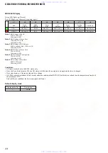
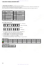
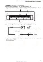
Jig Connection/Connectors
Destination
Name
CDC
UART connector (for design)
PANA-BUS connector
PC
RS-232C connector (for design)
H/U
PANA-BUS connector (for design)
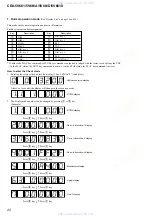
Use of Each Switch and LED on the Jig
Name
Type
Use
SCAN
Blink
t
Disc scan
MODE LED
Lit
t
All scan
(Number to be adjusted)
SHUFFLE
Blink
t
Disc shuffle
Lit
t
All shuffle
DTMS
Display
7 seg LED
×
8
Aging count
Error
Rotary SW
12 steps
Operation mode selection
UART line selection
LINE
CDC: PC
y
CDC
JIG: PC
y
JIG
FL-CDC
Set CDC microcomputer to the Flash Rewrite mode.
Toggle SW
FL-JIG
Set Jig microcomputer to the Flash Rewrite mode.
CONTROL
Control voltage
RS-232C
To use straight cable: STRAIGHT
CABLE SELECT
To use cross cable: CROSS
Head Unit selection
H/U
RADIO: Radio connection mode
JIG: PANA-BUS standalone mode
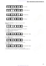
Push SW
1 to16
Execution keys according to each operation mode
RST
Reset key for Jig and CDC microcomputers
However, CDC cannot be reset unless the UART connector is connected.
www. xiaoyu163. com
QQ 376315150
9
9
2
8
9
4
2
9
8
TEL 13942296513
9
9
2
8
9
4
2
9
8
0
5
1
5
1
3
6
7
3
Q
Q
TEL 13942296513 QQ 376315150 892498299
TEL 13942296513 QQ 376315150 892498299


