– 9 –
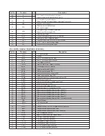
Pin No.
Pin name
I/O
Description.
37
VCTL
I
VCO2 control voltage input
38
PCO
O
Charge-pump output to master PLL
39
FILO
O
Filter output to master PLL
40
FILI
I
Filter input for master PLL
41
AVSS
–
Analog ground
42
CLTV
I
Control voltage input for VCO
43
AVDD
–
Analog power supply
44
RF
I
EFM signal input
45
BIAS
I
Asymmetry circuit constant current input
46
ASYI
I
Asymmetry comparate voltage input
47
ASYO
O
EFM full swing output (“L” =VSS, “H” =VDD)
48
ASYE
I
Asymmetry circuit ON/OFF (“L”=OFF, “H”=ON)
49
WDCK
O
D/A interface Word clock f=2fs (Not used)
50
LRCK
O
D/A interface LR clock output f=Fs
51
LRCKI
I
D/A interface LR clock input f=Fs
52
PCMD
O
D/A interface Serial data output
53
PCMDI
I
D/A interface Serial data input
54
BCK
O
D/A interface Bit clock output
55
BCKI
I
D/A interface Bit clock input
56
VSS
–
Ground
57
VDD
–
+5V power supply
58
GTOP
–
Not used
59
XUGF
–
Not used
60
XPLCK
O
EFM decoder PLL clock output
61
GFS
O
“H” Playback EFM sync and interpolation protection timming much
62
RFCK
O
Read Frame Clock signal output
63
C2PO
–
Not used
64
XRAOF
O
Internal RAM overflow detection signal output (Not used)
65
MNT3
–
Not used
66
MNT1
–
Not used
67
MNT0
–
Not used
68
XTSL
–
Not used
69
FSTT
O
2/3 divider output (Not used)
70
C4M
O
4.2336MHz output(Not used)
71
DOUT
O
Digital audio signal output
72
EMPH
O
Playback disc output in emphasis mode
73
EMPHI
I
“H” =Input when de-emphasis ON
74
WFCK
O
Write Frame Clock signal output
75
SCOR
O
Sub-code sync output
76
SBSO
O
Sub-P through Sub-W serial output
77
EXCK
I
Clock input for SBSO read-out
78
VSS
–
Ground
79
VDD
–
+5V power supply
80
SYSM
I
System mute input (Connected to ground)
81
—
–
Not used
82
AVSS
–
Analog ground
83
AVDD
–
Analog power supply
84
AOUT1
O
Lch analog output
85
AIN1
I
Lch opamp input
86
LOUT1
O
Lch line output
87
AVSS
–
Analog ground
88
XVDD
–
Master clock power supply
89
XTAI
I
X’tal oscillator circuit input
90
XTAO
O
X’tal oscillator circuit output


