— 7 —
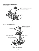
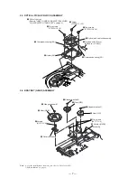
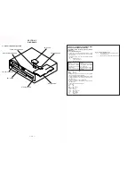
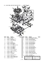
2-3. OPTICAL PICK-UP BLOCK ASSEMBLY
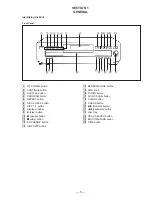
2-4. BRACKET (GEAR) ASSEMBLY
Note :
As for the installation of the main gear, refer to “Note for MAIN
GEAR installation” on page 4.
5
Two screws
(PTPWH 2.6
×
6)
4
Two screws
(PTPWH 2.6
×
6)
7
Compression spring(BU)
1
Pull out the tray.
(Refer to "HOW TO OPEN THE DISC TRAY WHEN
POWER SWITCH TURNS OFF" on page 4.)
6
Holder (BU)
8
Compression spring (BU)
9
Optical pick-up block assembly
2
Flat type wire(16 core)
(BD board, to CN101)
3
Screw
(PTPWH 3
×
12)
6
Rotary encoder
4
Gear (MAIN)
2
Gear (REV)
8
Gear (U/D)
0
Bracket (GEAR)
assembly
3
Stopper washer(5)
1
Stopper washer(5)
7
Stopper washer(5)
5
Screws
(BVTP 3
×
8)
9
Five screws
(BVTP 3
×
8)


