background image

SONY CAV-CVS12ES (US) 3-198-136-

11

(1)

3-198-136-

11

(1)

Component Video 

Switcher

 2007 Sony Corporation

CAV-CVS12ES

Installation Manual

Owner’s Record

The model and serial numbers are located on the rear panel.  Record the model and 

serial numbers in the spaces provided below. Refer to them whenever you call upon 

your Sony dealer regarding this product. 


Model No. 

Serial No. 

Содержание CAV-CVS12ES - Component Video Switcher

Страница 1: ...AV CVS12ES Installation Manual Owner s Record The model and serial numbers are located on the rear panel Record the model and serial numbers in the spaces provided below Refer to them whenever you call upon your Sony dealer regarding this product Model No Serial No ...

Страница 2: ... not expressly approved in this manual could void your authority to operate this equipment Important Safety Instruction 1 Read these instructions 2 Keep these instructions 3 Heed all warnings 4 Follow all instructions 5 Do not use this apparatus near water 6 Clean only with dry cloth 7 Do not block any ventilation openings Install in accordance with the manufacturer s instructions 8 Do not install...

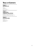
Страница 3: ...ures 4 Unpacking 5 Parts and Controls 6 Chapter 2 Setting up the Component Video Switcher Installing the Component Video Switcher 8 Hooking up the Component Video Switcher 10 Chapter 3 Other Information Precautions 12 Troubleshooting 13 Specifications 14 ...

Страница 4: ...AV CVS12ES Component Video Switcher The Component Video Switcher allows you to Distribute HD video signals in up to twelve zones Up convert up to four composite video signals to component video signals for higher quality Control the source component in synchronization with the CAV M1000ES via RS 232C commands Control the source component via IR control signal Transmit video signals throughout the ...

Страница 5: ... US Getting Started Unpacking The CAV CVS12ES Component Video Switcher includes the following CAV CVS12ES Component Video Switcher AC power cord Installation Manual this manual Rack mount brackets 2 ...

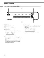
Страница 6: ...r selected for the zone lights up When the zone does not select any source component no SOURCE indicator lights up Note When you assign two or more source components to the same source number the assigned source numbers of the SOURCE indicator blink as an error indication Front panel of the Component Video Switcher Parts and Controls SOURCE selector Turn to select the source component Each time yo...

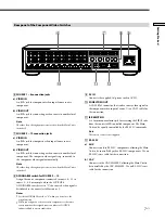
Страница 7: ...signal automatically Note The video loop through output is not active when the Main Unit is turned off ASSIGNABLE switch for SOURCE 9 12 Assign the source component connected to source 9 12 to source 1 8 For example when the SOURCE 9 ASSIGNABLE switch is set to 1 the source 9 video signal is distributed to the zone selected for source 1 Notes Set the ASSIGNABLE switch to 0 when you do not use the ...

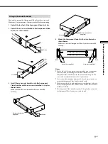
Страница 8: ...ion prevent heat buildup and prolong the life of the unit Place a board under the Component Video Switcher if it is located on a carpet to allow adequate ventilation on the bottom Make sure the weight is equally distributed on each of its four feet Do not place anything on the top of the Component Video Switcher that might block the ventilation holes and cause malfunction Do not place anything on ...

Страница 9: ...to the rack as shown below Make sure that the Component Video Switcher is installed securely Rack POWER 1 2 3 4 5 6 7 8 9 10 11 12 1 2 3 4 5 6 7 8 9 10 11 12 ZONE SOURCE Screws not supplied Screws not supplied Rack Notes Use the M4 11 32 inch 8mm screws attached to the Component Video Switcher for installing the rack mount brackets onto the Component Video Switcher In case the screws are missing u...

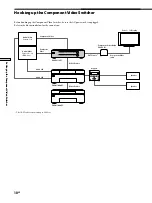
Страница 10: ...gged Refer to the illustration below for the connection Speaker The CAT5 cable can extend up to 300 feet Audio Video Source 1 8 Component Video Audio L R CAV M1000ES CAV M1000ES CAV CVS12ES RS 232C cable RS 232C cable CAT5 cable Component Video Balun CAV CVB1 Keypad Zone 1 12 Display Speaker Component Video cable Audio Video Source 9 12 VHS etc Audio L R Composite Video ...

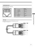
Страница 11: ... 5 11V White Blue Pin 6 GREEN Y T Green Pin 7 RED Pr R White Brown Pin 8 RED Pr T Brown CAT5 cable Before installation be sure to verify the CAT5 wiring connection is correct Use Category 5e or Category 6 cable White Orange Wire color Orange White Green Blue White Blue Green White Brown Brown 1 Pin No 2 3 4 5 6 7 8 White Orange Wire color Orange White Green Blue White Blue Green White Brown Brown ...

Страница 12: ...ment Place the unit in a location with adequate ventilation to prevent heat build up in the Component Video Switcher Do not place the unit on a soft surface such as a rug that might block the ventilation holes on the bottom Do not place the unit in a location near heat sources or in a place subject to direct sunlight excessive dust or mechanical shock On cleaning Clean the cabinet panel and contro...

Страница 13: ...ear properly Check that the Component Video Switcher is connected correctly For details on how to make the connection refer to Hooking up the Component Video Switcher on page 10 The multiple SOURCE indicators blink Two or more source components are assigned to the same source number Set the ASSIGNABLE switch to the appropriate source number The source does not change even after turning the SOURCE ...

Страница 14: ...R input accept 40 kHz IR modulation frequency Power requirements 120 V AC 60 Hz Power consumption 33 W Operating temperature 0 C to 40 C 32 F to 104 F Dimensions 435 100 290 mm 17 1 4 4 11 1 2 inches w h d including projecting parts Mass 4 5 kg 9 lbs 15 oz excluding AC power cord Design and specifications are subject to change without notice ...

Страница 15: ......

Страница 16: ...Sony Corporation Printed in Malaysia ...

Отзывы: