background image

50

Chapter 2  Menu

[C61]

 CONV FINE ADJUST menu (BVM-

D32E1WU/D32E1WE/D32E1WA only)

Adjust the convergence finely at each adjustment point
on the screen with the MANUAL knobs.
The signal format and screen size for the adjustment
are displayed on the top of the screen.
ADJUST... : Adjust the convergence. 

÷

[C611]

 (It

may take some time to change to the next menu.)
Use appropriate knobs and buttons in each
adjustment as described below.
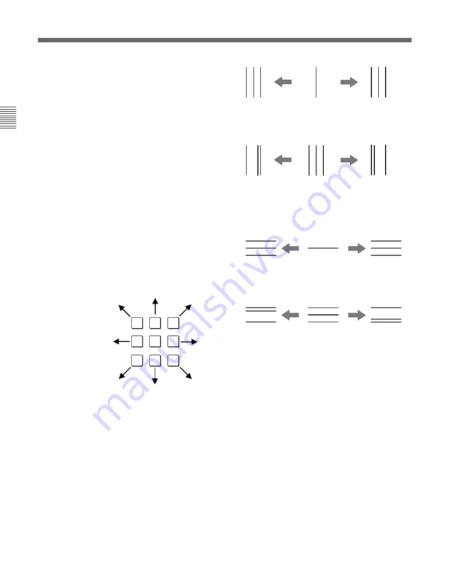
H CONV: CONTRAST KNOB:  Adjust the

horizontal convergence with the CONTRAST
knob.

H G CONV: BRIGHT KNOB:  Adjust the

horizontal convergence with the BRIGHT
knob.

V CONV: CHROMA KNOB:  Adjust the vertical

convergence with the CHROMA knob.

V G CONV: PHASE KNOB:  Adjust the vertical

convergence with the PHASE knob.

CURSOR POSITION: 10KEY:  Move the cursor

using the numeric keypad (except the 5 button)
as illustrated below. Turn on/off the cursor
using the 5 button.

TO CANCEL: MENU KEY:  Press the MENU

button to clear the adjusted data and return to
the previous menu.

TO CONFIRM: ENTER KEY:  Press the

ENTER or Ent button to confirm the adjusted
data.

[C611]

 ADJUST menu

Adjust the convergence at the cursor position using the
CONTRAST (H CONV), BRIGHT (H G CONV),
CHROMA (V CONV) and PHASE (V G CONV)
knobs.  Move the cursor using the numeric keypad.
H CONV: Turn the CONTRAST knob clockwise to

move the R beam to the right and the B beam to the
left; counterclockwise to move the R beam to the
left and the B beam to the right.

H G CONV: Turn the BRIGHT knob clockwise to

move the G beam to the left; counterclockwise to
move the G beam to the right.

V CONV: Turn the CHROMA knob clockwise to

move the R beam upward and the B beam
downward; counterclockwise to move the R beam
downward and the B beam upward.

V G CONV: Turn the PHASE knob clockwise to

move the G beam downward; counterclockwise to
move the G beam upward.

To reset the convergence to the condition before
adjustment
You can reset the adjusted condition to the one before
adjustment by pressing the corresponding MANUAL
button.

To finish the adjustment
Press the ENTER or Ent button.  The adjusted data is
stored in the memory and the screen returns to the
CONV FINE ADJUST menu (

[C61]

). (It may take

some time to change to the previous menu.)

To cancel the adjustment
Press the MENU button.  The adjusted data is cleared
and the screen returns to 

[C61]

.  (It may take some

time to change to the previous menu.)

When you want to erase characters from the screen
while adjusting the convergence
Press the 

[F1]

 button. The characters disappear.  To

display characters, press the 

[F1]

 button again.

1

2

3

4

5

6

7

8

9

The cursor moves in
the direction of the
arrow corresponding
to the pressed button.

R  G  B

B  G  R

R
G
B

B    GR

B G    R

B  G  R

B

G

R

R
G
B

RGB

R

G

B

R

G
B

R

G

B

[C6]

 Adjusting Geometry and Convergence (SET UP 6) — ALIGNMENT Menu

Turn
clockwise.

Turn
counterclockwise.

Turn
clockwise.

Turn
counterclockwise.

Turn
clockwise.

Turn
counterclockwise.

Turn
clockwise.

Turn
counterclockwise.

Содержание BVM-D20F1U, BVM-D20F1E, BVM-D20F1A, BVM-D24E1WU, BVM-D24E1WE, BVM-D24E1WA, BVM-D32E1WU, BVM-D32E1WE, BVM-D32E1WA

Страница 1: ...OPERATION MANUAL English 1st Edition Revised 7 Serial No 2000001 and Higher TRINITRON COLOR VIDEO MONITOR BVM D20F1U D20F1E D20F1A BVM D24E1WU D24E1WE D24E1WA BVM D32E1WU D32E1WE D32E1WA ...

Страница 2: ...n risque d explosion si la pile est mal insérée Remplacer la pile uniquement par une pile de même type ou de type équivalent recommandé par le fabricant Jeter les piles usées conformément aux instructions du fabricant VORSICHT Es besteht Explosionsgefahr wenn die Batterie inkorrekt eingelegt wird Es darf nur eine identische oder eine vom Hersteller empfohlene Batterie des gleichen Typs eingesetzt ...

Страница 3: ...r the customers in Europe BVM D20F1E D20F1A BVM D24E1WE D24E1WA BVM D32E1WE D32E1WA This product with the CE marking complies with both the EMC Directive 89 336 EEC and the Low Voltage Directive 73 23 EEC issued by the Commission of the European Community Compliance with these directives implies conformity to the following European standards EN60950 Product Safety EN55103 1 Electromagnetic Interfe...

Страница 4: ...ntrario el monitor puede no cumplir con los reglamentos de la FCC o de la directiva 89 336 EEC de la Comunidad Europea Nota Assicurarsi di usare il cavo di alimentazione in dotazione per questo monitor altrimenti il monitor può non essere conforme alle norme FCC o alla Direttiva CEE 89 336 For the customers in United Kingdom BVM D20F1E D20F1A BVM D24E1WE D24E1WA BVM D32E1WE D32E1WA WARNING THIS AP...

Страница 5: ...s in einem Gestell a Erhöhte Umgebungstemperatur bei Betrieb Wird das Gerät in einem geschlossenen Gestell oder einem Gestell mit mehreren anderen Geräten installiert kann die Umgebungstemperatur um das Gestell höher sein als die normale Umgebungstemperatur im Raum Achten Sie daher bitte besonders darauf das Gerät in einer Umgebung zu installieren in der die Temperatur nicht über die vom Herstelle...

Страница 6: ......

Страница 7: ...NFIGURATION Menu 36 Setting Lists in the INPUT CONFIGURATION Menu 37 C2 Assigning the Remote Control Functions SET UP 2 REMOTE Menu 40 Overview 40 Structure of the REMOTE Menu 40 Setting Lists of the REMOTE Menu 41 C3 Setting the Password SET UP 3 PASSWORD Menu 42 Overview 42 Structure of the PASSWORD Menu 42 Setting Lists of the PASSWORD Menu 42 C4 Setting the Channel Selection Method Power Up Co...

Страница 8: ...sts of the EXTEND Menu 55 Structure of the EXTEND Menu 55 D Monitor Memory Card Data Operations MEMORY CARD Menu 57 Overview 57 Structure of the MEMORY CARD Menu 57 Setting Lists of the MENU CARD Menu 57 E Monitor to Monitor Data Copy COPY FROM Menu 58 Overview 58 Structure of the COPY FROM Menu 58 Setting Lists of the COPY FROM Menu 58 F Displaying Information About the Monitor STATUS Menu 59 Ove...

Страница 9: ...s about this unit contact your authorized Sony dealer On rack mounting When the monitor is mounted on a rack the temperature around the monitor may rise due to heat generated from other equipment and reduced air circulation causing damage to the monitor To prevent this keep ventilation holes install a ventilation fan or take other effective countermeasures so that the temperature around the monito...

Страница 10: ... setup and adjustment state Setup and adjustment with the Monitor Memory Card You can use an optional BKM 12Y Monitor Memory Card to save and load monitor setup and adjustment data via the BKM 10R 11R Monitor Control Unit If your system includes more than one monitor you can use the monitor memory cards to exchange data between monitors This makes it easy to put all monitors in your system into th...

Страница 11: ...n menus Compatible with the ISR Interactive Status Reporting system Has both RS 485 serial remote and relay contact parallel remote control connectors Built in test signal generator for crosshatch 100 white signal 20 gray signal gray scale and PLUGE Picture Line Up Generating Equipment Built in Caption Vision decoder Pulse cross function for simultaneous checking of the horizontal and vertical syn...

Страница 12: ... channels and three analog channels BKM 24N NTSC Decoder Adaptor Includes decoders for analog composite NTSC signals and input output connectors for six analog channels BKM 25P PAL Decoder Adaptor Includes decoders for analog composite PAL signals and input output connectors for six analog channels BKM 26M PAL M Decoder Adaptor Includes decoders for analog composite PAL M signals and input output ...

Страница 13: ...decoder adaptors When multiple decoder adaptors for NTSC or PAL format are installed their priority is as in the following table Example To monitor the composite NTSC signal when the BKM 24N and BKM 27T are installed the input composite NTSC signal is always decoded by the BKM 24N Y C PAL BKM 42HD HD SDI Input Adaptor Adaptor name BKM 48X1 HD Analog Expansion Adaptor Composite NTSC Composite PAL C...

Страница 14: ...onent 525 625 Composite SECAM YPBPR 525 625 GBR 525 625 Y C NTSC Serial digital input Analog input BKM 20D SDI 4 2 2 Decoder Adaptor Number of analog input Number of digital inputs Y C PAL M 3 3 6 6 6 6 3 3 BKM 22X SDI Input Expansion Adaptor 6 Signal can be reproduced with this adaptor Signal can be reproduced when using this adaptor together with an adaptor marked with Signal format HD SDI YPBPR...

Страница 15: ...tor inside the monitor then tighten the two screws to secure the adaptor Note When installing a decoder adaptor in an input option slot on the rear of the monitor or fitting a cover plate to an unused slot always do such operation in order from the rightmost slot If some adaptors are already installed first of all remove them and then do the installing operation in order from the rightmost slot Wh...

Страница 16: ...D24E1WE D24E1WA D32E1WU D32E1WE D32E1WA BVM D20F1U D20F1E D20F1A 5 OPTION connector 1 Tally lamp 2 POWER lamp 3 STANDBY lamp 4 OVER LOAD lamp 5 OPTION connector 1 Tally lamp 2 POWER lamp 3 STANDBY lamp 4 OVER LOAD lamp The illustration above shows the BVM D24E1WU D24E1WE D24E1WA ...

Страница 17: ...en the STANDBY lamp 3 is blinking the monitor cannot be put into operation mode internal data initialization is taking place Wait until the STANDBY lamp 3 is steadily lit 3 STANDBY lamp Lights when the monitor is in standby mode The monitor will be in standby mode under the following conditions The MAIN POWER switch on the rear panel is turned on the STANDBY lamp will blink for a few moments after...

Страница 18: ...log input output connectors 7 REMOTE 1 connectors 8 REMOTE 2 connector º CONTROL UNIT connector 1 MAIN POWER switch 2 AC IN socket 3 Fuse 4 Deflection option slot Digital uniformity adaptor installed as standard 9 ISR connector 5 Analog input output connectors 6 Input option slots 7 REMOTE 1 connectors 8 REMOTE 2 connector º CONTROL UNIT connector 6 Input option slots The illustration above shows ...

Страница 19: ... been installed at the factory For the BVM D20F1U D20F1E D20F1A this slot is provided for future use Attach the AC Plug holder to the AC power cord and connect it to the AC IN socket so that the cord does not come loose AC Plug holder supplied AC power cord supplied 5 Analog input output connectors GBR signals component signals Y PB PR or composite sync signals can be fed in the IN connectors The ...

Страница 20: ...E menu see C2 Assigning the Remote Control Functions SET UP 2 REMOTE Menu on page 40 To switch each function between on and off or between enable and disable change pin connections in the following way ON or enabled Short each pin and pin 9 together OFF or disabled Leave each pin open 9 ISR Interactive Status Reporting connector female D sub 9 pin Connect to the ISR system º CONTROL UNIT connector...

Страница 21: ... For the functions of the function buttons in case of SHIFT OFF and SHIFT ON see pages 17 and 18 1 Monitor memory card insertion slot 2 SHIFT button 5 POWER switch 6 DEGAUSS button 7 DISPLAY UNIT connector rear 8 Numeric keypad 9 MANUAL adjustment buttons and knobs 3 Function buttons 4 Menu operation buttons For more information about menu operation see Basic Menu Operations on page 22 5 POWER swi...

Страница 22: ...alues and characters entered ENTER button of the menu operation buttons 4 has the same function Del button Deletes the values and characters entered INPUT 1 2 3 Del 4 5 6 0 7 8 9 Ent CONTRAST button and knob BRIGHT button and knob CHROMA button and knob 9 MANUAL adjustment buttons and knobs Each press of one of these buttons turns the button s green LED on or off When the corresponding button is o...

Страница 23: ...olor burst signal Note The MONO button does not function with the GBR signal input ADDRESS button When this button is pushed in ON the ADDRESS menu appears on the screen By using the ADDRESS menu operation conditions for multiple monitors are set For more information about the ADDRESS menu see Selecting the Monitor to Control ADDRESS Menu on page 60 F2 button When this button is pushed in ON you c...

Страница 24: ...NT SYNC Notes When INT SYNC is selected use a component or YC signals including a sync signal on the Y signal and use GBR signal including a sync signal on the G signal To monitor serial digital signals always select INT SYNC BLUE ONLY button When this button is pushed in ON red and green signals are cut and only the blue signal is displayed as a monochrome picture It makes it easy to adjust CHROM...

Страница 25: ...Hz 25 MHz 720 60P 25 MHz 25 MHz 25 MHz An empty frame in the table means that the signal cannot be input or the aperture modification can not operate for that signal even if it is input The aperture modification frequency is 25 MHz when the signal is input via the analog input output connectors equipped as standard The BKM 41HD and BKM 42HD with the serial number 2100001 to 2110000 cannot receive ...

Страница 26: ...r Memory Card EJECT button Press the EJECT button to eject the monitor memory card Take out the monitor memory card Inserting ejecting the BKM 12Y Memory Monitor Card Proceed as illustrated to insert and eject an optional BKM 12Y Monitor Memory Card For information about operations on monitor memory card data see D Monitor Memory Card Data Operations MEMORY CARD menu on page 57 Note Do not eject t...

Страница 27: ...mask with the supplied 4 3 mask Installing the 4 3 mask 1 Remove the 16 9 mask by pulling the top side out and then lifting up from the bottom side 2 Install the 4 3 mask supplied by inserting the bottom side and then pressing the top side in Replacing the 16 9 mask Remove the 4 3 mask and replace the 16 9 mask using the same procedures as those for installing the 4 3 mask ...

Страница 28: ...NUAL MANUAL MANUAL MANUAL UP MENU DOWN ENTER 6 Ent button 4 PHASE knob 2 MENU button 1 UP DOWN buttons 3 ENTER button 5 Numeric keypad 7 Del button 2MENU button Displays the menus Goes back to the menu of the upper level on the Main Menu goes back to the normal picture 3ENTER button Executes the items selected and 6Ent button settings 4PHASE knob By turning this knob clockwise the cursor moves upw...

Страница 29: ...enu numbers Thus the menu number is counted without menus which do not require explanation Menu Operation Follow the steps described below to display the menu and perform the adjustment or setup you wish 1 Press the MENU button 2 The Menu List is displayed 2 Using the UP DOWN buttons 1 or PHASE knob 4 move the cursor to the desired item Example select the SET UP menu by pressing the DOWN button 3 ...

Страница 30: ... S A F E A R E A D I S P L A M O D Y O F F E p A P E R T U R E O F F V A L U E 1 0 0 1 0 C H I N P U T C O N F I G U R A T I O N F O R M A T Y P B P R S L O T N O S L O T 2 I N P U T N O 1 Y C S E P 3 L I N E S C O M B S Y N C M O D E I N T S C R E E N M O D E 4 3 N O R M S A F E A R E A D I S P L A M O D Y O F F E p Choosing one of two or more selections Selecting in yellow text 1 Using the UP DO...

Страница 31: ...D I S P L A M O D Y O F F E p C H A N N E L N A M E P R O G E D I T C A M V T R N E W N A M E p 2 Press the ENTER or Ent button is displayed in yellow The indicates the position where character input is possible 3 Select the character you wish to enter using the UP DOWN buttons or PHASE knob When you press the UP button or turn the PHASE knob clockwise the characters and symbols appear in the orde...

Страница 32: ...p address number so that when several monitors are connected together via serial remote ports the control panel can select which monitor to control To display or exit the ADDRESS menu press the ADDRESS button The method of choosing menu items and changing settings is the same as with the other menus For information about the ADDRESS menu see Selecting the Monitor to Control ADDRESS Menu on page 60...

Страница 33: ...page 28 Sets the color temperature page 30 A menu group for performing monitor setup consisting of the following Sets the input channel page 35 Sets the remote control functionality page 40 Sets passwords for menus page 42 Sets the input channel selection method power up conditions and decoder page 44 Sets data about the screen display page 46 Adjusts the screen convergence and geometry page 48 Ad...

Страница 34: ...on each setting list is preceded by a menu number These numbers are not displayed on the screen For more information about the menu number see About menu numbers on page 23 Overview The arrow mark refers you to another setting list that appears after you make the setting or to an operation that is carried out as a result of the setting When there is no arrow mark the menu does not have any sub lis...

Страница 35: ...0 full field 8 color bar white yellow cyan green magenta red blue and black 8COLOR BAR 75 75 full field 8 color bar with 100 white signal effective for 15K signal only 7COLOR BAR 100 100 full field 7 color bar white yellow cyan green magenta red and blue with 100 white signal not selectable for 15K signal SMPTE COLOR BAR SMPTE standard color bar effective for 15K signal only EIA COLOR BAR EIA stan...

Страница 36: ...0 PHILIPS PM 5639 THOMA TF6 B Adjusting the Color Temperature COLOR TEMP ADJ Menu The color temperature is adjusted with the COLOR TEMP ADJ menu The color temperature can be set either commonly to all channels STD COL1 and COL2 menus or individually for each channel CH SET menu Use the factory setting value or the adjusted value as an original value to shorten the adjustment time Color temperature...

Страница 37: ...11 X Y LOW LIGHT 20IRE HIGHLIGHT 100IRE D65 D93 STD COL1 COL2 CH SET D65 D93 MONITOR ADDRESS B1321 SET PROBE ON THIS CRT B12121 SET PROBE ON CRT FILE NAME B1331 OTHER MONITOR B132 OTHER VALUE B131 X Y L INT EXT ADJUST ORIGINAL VALUE SIGNAL ADJUST B1211 ANALYZE B1212 SONY BKM 14L B121 GRASEBY SLS9400 MINOLTA CA 100 PHILIPS RM5639 THOMA TF6 B122 PROBE B12 Structure of the COLOR TEMP ADJ Menu Level 1...

Страница 38: ... or bias with the CHROMA knob LUMINANCE PHASE KNOB Adjust luminance with the PHASE knob To reset RED GREEN BLUE to the value before adjustment When you are adjusting the gain or bias using the MANUAL adjustment knobs you can reset the setting to the one before adjustment by pressing the corresponding MANUAL button To reset all of settings at the same time press the PHASE button Note You cannot res...

Страница 39: ... read the color system and luminance value SET PROBE ON THIS CRT PRESS ENTER Attach the BKM 14L on the center of the CRT and press the ENTER or Ent button B12121 Once the BKM 14L has carried out calibration the BKM 14L can start analyze the monitor s performance B12121 SET PROBE ON THIS CRT menu Display the color system and luminance readout values from the BKM 14L system at the bottom of the CRT ...

Страница 40: ... KNOB Adjust the G gain or bias with the BRIGHT knob BLUE CHROMA KNOB Adjust the B gain or bias with the CHROMA knob LUMINANCE PHASE KNOB Adjust luminance with the PHASE knob To reset RED GREEN BLUE to the value before adjustment When you are adjusting the gain or bias you can reset the setting to the one before adjustment by pressing the corresponding MANUAL button To reset all of settings at the...

Страница 41: ... slots are numbered from the left as seen when facing the rear panel with the REMOTE connectors slot being number 1 the input option slots numbers 2 to 5 and the analog input connectors slot being number 6 The connectors for each slot are numbered 1 to 6 from the top Assigning the signal type and format The signal type and format which can be assigned to each channel number vary depending on what ...

Страница 42: ... COMPOSITE C111 YC C111 COMPONENT C112 SDI C113 TRAP BPF 2 LINES COMB 3 LINES COMB INT EXT 16 9 NORM 16 9 UNDR 4 3 NORM 4 3 UNDR SIZE H SIZE V SIZE H POSITION SHAPE 4 3 AREA MARKER 4 3 BLANKING NTSC PAL PAL M SECAM AUTO PROG EDIT CAM VTR NEW NAME PRESET CH SET STD COL1 COL2 CH SET 1080I 1035I OTHER CH OTHER MONITOR C171 MEMORY CARD C172 MONITOR ADDRESS C1711 FILE NAME C1721 YPBPR SMPTE EBU N10 YPB...

Страница 43: ...will be stored as information about the signal to be connected to this channel FILTER Switch the filter operation OFF or ON when the monochrome display is selected CHANNEL NAME Give the channel a name C15 Setting Lists in the INPUT CONFIGURATION Menu CONTROL Use if either PRESET or CH SET values are used for the CONTRAST BRIGHT CHROMA PHASE settings PRESET Use values common to all channels CH SET ...

Страница 44: ...ES COMB filter 3 LINES COMB Select 3 LINES COMB filter C13 SCREEN MODE menu Select the scan size 16 9 NORM Overscanned 16 9 aspect ratio 16 9 UNDR Underscanned 16 9 aspect ratio 4 3 NORM Overscanned 4 3 aspect ratio 4 3 UNDR Underscanned 4 3 aspect ratio C14 SAFE AREA MODE menu Set the safe area display modes SIZE Select the safe area mode 16 9 80 Displays a 80 safe area with 16 9 aspect ratio 16 ...

Страница 45: ...CH SET Use data for each individual channel C17 COPY FROM menu Select the source to be copied from OTHER CH Copy data from another channel Enter the channel number OTHER MONITOR Copy data from a BVM DxxE DxxF series monitor C171 MEMORY CARD Copy data from a memory card C172 C171 OTHER MONITOR menu Enter the address number of the source monitor MONITOR ADDRESS Enter the address number of the monito...

Страница 46: ...unctions It is possible to simultaneously use the BKM 10R 11R Monitor Control Unit REMOTE 1 and REMOTE 2 for control but commands from REMOTE 2 have priority Therefore it is impossible for the BKM 10R 11R or REMOTE 1 to change items set by REMOTE 2 There is no priority order between commands from REMOTE 1 and the BKM 10R 11R control panel About monitor address and group numbers The BKM 10R 11R Mon...

Страница 47: ...you want to change the function The factory settings for each pin are given below C221 1 PIN CH01 2 PIN CH02 3 PIN EXT SYNC 4 PIN MONO 5 PIN SAFE AREA 6 PIN unused 7 PIN unused 8 PIN TALLY C221 1 8 PIN menu 1 2 Assign a function to the selected pin CH Select a channel number Enter the desired channel number with the numeric keypad Set to unused UNDER SCAN Set underscan on or off 16 9 Set a 16 9 as...

Страница 48: ...d when an attempt is made to select a menu item for which the password has been applied Then enter the password using the numeric keypad If the password is not entered correctly If an incorrect password is entered the display returns to the menu of the previous level Overview Structure of the PASSWORD Menu Setting Lists of the PASSWORD Menu This section explains the setting lists displayed in the ...

Страница 49: ... menu Change the password ENTER PASSWORD Enter a new password C3111 C3111 ENTER PASSWORD menu Create a new password RE ENTER PASSWORD Enter the new password again and press the ENTER button The password is registered To change it press the MENU button Return to C31 C312 APPLY PASSWORD menu Choose whether or not to apply the password to each menu CONTROL PRESET ADJ Select YES or NO COLOR TEMP ADJ S...

Страница 50: ...this the delay time between power up and degaussing can be set for each monitor independently Residual subcarrier detection RESIDUAL SC SW menu when using the BKM 24N 25P It is possible to detect residual subcarrier signals from phase change by setting the decoder adpator s residual subcarrier switch on Auto color control ACC SW menu when using the BKM 27T Selects if the ACC Auto Color Control cir...

Страница 51: ...nd ENTER Ent buttons the monitor displays channel xy a two digit channel number When multiple monitors are connected by a serial remote connection this setting will be common to all the monitors It is not possible to change the setting for individual monitors STANDBY MODE Select the power up condition when the MAIN POWER switch is turned on OFF or ON ON Standby mode OFF Operation mode DEFAULT CH S...

Страница 52: ...f information that will be displayed on the screen and how that information will be displayed The types of information that can be set are as follows Overview Structure of the ON SCREEN SET Menu Caption vision CAPTION VISION menu SDI signal ancillary data blanking ANCILLARY DATA menu when the SDI signal is displayed Display mode and position of the signal format FORMAT DISPLAY and POSITION menus D...

Страница 53: ...CH NAME POSITION Select the display position for the channel name C54 C51 CAPTION VISION menu Select the caption display mode OFF Not displayed CAPTION 1 Displayed in CAPTION 1 mode CAPTION 2 Displayed in CAPTION 2 mode TEXT 1 Displayed in TEXT 1 mode TEXT 2 Displayed in TEXT 2 mode C52 FORMAT DISPLAY and POSITION menus FORMAT DISPLAY menu Select the display mode of the signal format AUTO Disappea...

Страница 54: ... explains the setting lists displayed in the menu How to read the setting lists For purposes of explanation each setting list is preceded by a menu number These numbers are not displayed on the screen For more information about the menu number see About menu numbers on page 23 C6 Adjusting Geometry and Convergence SET UP 6 ALIGNMENT Menu Adjusting the position and size of the picture ALIGNMENT men...

Страница 55: ...N Correct side pincushion distortion H PIN BAL Correct the balance of side pincushion distortion H CORNER PIN Correct pincushion distortion at the sides of the picture H CORNER S Correct S pincushion distortion at the sides of the picture H KEY Correct trapezoid distortion H KEY BAL Correct the balance of trapezoid distortion C6 ALIGNMENT menu 3 3 Adjust the convergence with the UP and DOWN button...

Страница 56: ...wise to move the R beam to the left and the B beam to the right H G CONV Turn the BRIGHT knob clockwise to move the G beam to the left counterclockwise to move the G beam to the right V CONV Turn the CHROMA knob clockwise to move the R beam upward and the B beam downward counterclockwise to move the R beam downward and the B beam upward V G CONV Turn the PHASE knob clockwise to move the G beam dow...

Страница 57: ... SIGNAL MANUAL C73 AUTO FULL POINTS C74 AUTO ONE POINT C75 ORIGINAL VALUE SIGNAL WHITE UNIFORMITY 1 2 C7 LANDING ADJUST WHITE UNIFORMITY 2 2 C7 DIGITAL UNIFORMITY ADJ INPUT CONFIGURATION C1 REMOTE C2 PASSWORD C3 SYSTEM CONFIGURATION C4 ON SCREEN SET C5 ALIGNMENT C6 WHITE UNIFORMITY C7 EXTEND MENU C8 DIRECTION C711 FINE ADJUST C712 SET PROBE ON CURSOR C721 EXT INT ADJUST C731 CURSOR H SIZE CURSOR V...

Страница 58: ...e screen size from 16 9 NORM 16 9 UNDR 4 3 NORM and 4 3 UNDR Note 4 3 NORM and 4 3 UNDR can be combined with 480 60P 480 60I 575 50P and 570 50I only SIGNAL Select the white signal to be used for adjustment EXT Use an external input signal When adjusting the gain input the appropriate signal INT Use an internal white signal C71 MANUAL menu Select the rough or fine adjustment of beam landing First ...

Страница 59: ...with the BRIGHT knob BLUE CHROMA KNOB Adjust the B gain with the CHROMA knob CURSOR POSITION 10KEY Move the cursor using the numeric keypad except the 5 button as illustrated below Turn on off the cursor using the 5 button 1 2 3 4 5 6 7 8 9 The cursor moves in the direction of the arrow corresponding to the pressed button CURSOR H SIZE Specify the horizontal size of the cursor 1 to 4 CURSOR V SIZE...

Страница 60: ... the screen returns to the WHITE UNIFORMITY menu 2 2 C7 2 Place the BKM 14L to the cursor displayed in the center of the screen The adjustment of the center of the screen starts IN PROGRESS appears during adjustment and the cursor returns to the point set in step 1 when the adjustment is completed 3 Move the BKM 14L to the cursor The adjustment of the specified point is performed IN PROGRESS appea...

Страница 61: ...onitor memory card MEMORY CARD menu Restarting the monitor RE START MONITOR menu Calibrating the internal signal level ADJ INT SIGNAL menu Improving the skew of the picture from the connected VCR VCR MODE menu Displaying the menu for maintenance MAINTENANCE menu Overview C8 Using Extended Functions SET UP 8 EXTEND Menu Level 1 Level 2 Level 3 Level 4 Level 5 1 This is displayed when the BKM 21D is...

Страница 62: ... card it must be formatted it with the FORMAT menu D4 System data and MEMORY CARD data D cannot be stored on the same memory card To store memory card data use another memory card The BKM 12Y monitor memory card has a capacity of 256 Kbytes It can store either system data for up to 8 monitors or 38 files of memory card data The input signal is not displayed during the data saving or loading C8121 ...

Страница 63: ...ving loading or deleting or the memory card formatting D Monitor Memory Card Data Operations MEMORY CARD Menu Reading data from a monitor memory card LOAD menu Deleting a file in a monitor memory card DELETE menu Formatting a monitor memory card FORMAT menu MEMORY CARD D SAVE D1 LOAD D2 DELETE D3 FORMAT D4 NEW NAME FILE NAME FILE NAME FILE NAME Confirmation message Confirmation message Main Menu L...

Страница 64: ...tting list that appears after you make the setting or to an operation that is carried out as a result of the setting When there is no arrow mark the menu does not have any sub list E COPY FROM menu Select the copy source monitor MONITOR ADDRESS Enter the monitor address number E1 E1 MONITOR ADDRESS menu Select the data to be copied Copy is carried out ALL Copy data for all menu settings CONTROL PR...

Страница 65: ...ON software version F3 STATUS menu 3 3 Data about circuit boards installed into the respective slots in the rear panel is displayed When the BKM 21D is installed in SLOT 2 the following is displayed When any optional boards are not installed EMPTY is displayed for SLOT 2 to SLOT 5 SLOT1 CONTROL SLOT2 SDI4 2 2 4FSC SLOT3 EMPTY SLOT4 EMPTY SLOT5 EMPTY SLOT6 VIDEO AMP SLOT7 DEFLECTION SLOT8 EMPTY BVM...

Страница 66: ...p address on its screen Notes To remotely control monitors connected in serial MONITOR ADDRESS or GROUP ADDRESS of monitors should be correctly set in the REMOTE menu For details of the REMOTE menu see C2 Assigning the Remote Control Functions SET UP 2 REMOTE Menu on page 40 In GROUP mode when the KEY PROTECT function is set to ON the LED on the pressed function button lights but it is deactivated...

Страница 67: ...ADDRESS button 2 Press the address number of the target monitor Press one digit address number on the numeric keypad when it is from 1 to 9 Press three digits address number press 0 button and then press the two digit address number when it is from 10 to 99 To select the monitors in the GROUP mode 1 Press the ADDRESS button 2 Press the F1 button 3 Press the group number of the target monitor Press...

Страница 68: ...15 625 kHz 45 kHz For details see Available Signal Formats on page 65 CRT BVM D20F1U D20F1E D20F1A Super fine pitch Trinitron 4 3 aspect ratio Aperture grille pitch 0 3 mm 90 degree deflection 30 6 mm diameter in line gun Effective picture size with 16 9 aspect ratio 386 218 mm 151 4 85 8 inches w h 443 mm 171 2 inches diagonal size Effective picture size with 4 3 aspect ratio 386 291 mm 151 4 111...

Страница 69: ...0 B 0 150 0 060 Input output connectors Video input BNC type 3 with loop through outputs G B R Composite 1 0 Vp p or non composite 0 7 Vp p Y Composite 1 0 Vp p or non composite 0 7 Vp p PB PR Non composite 0 7 Vp p Sync 0 3 V 6 dB positive negative tri level sync or 0 3 V 6 dB negative sync Sync input BNC type 1 with loop through output 0 3 to 8 Vp p positive negative tri level sync signal input ...

Страница 70: ...ral area bounded by a circle and less than 0 7 mm at any other point BVM D32E1WU D32E1WE D32E1WA Within a central area bounded by a circle with a diameter equal to the picture height Less than 0 5 mm with a central area bounded by a circle and less than 0 8 mm at any other point Standard luminescence BVM D20F1U D20F1E D20F1A D24E1WU D24E1WE D24E1WA 100 cd m2 at standard 1 Vp p 100 white signal BVM...

Страница 71: ...1 001 Active lines per frame Acquired safety regulations UL1950 CSA No 950 FCC Class A IC Class A DHHS DNHW TÜV EN60950 CE C tick Design and specifications are subject to change without notice Available Signal Formats 575 50I PAL 625 575 25 2 1 interlace 16 9 4 3 ITU 601 480 60I NTSC 525 483 30 2 1 interlace 16 9 4 3 ITU 601 575 50P 625 575 50 Progressive 16 9 4 3 480 60P 525 483 60 Progressive 16...

Страница 72: ...s Front Side Rear Dimensional Drawing BVM D20F1U D20F1E D20F1A Specifications Unit mm inches Front Side Rear 444 17 1 2 399 15 3 4 198 5 7 7 8 15 19 32 328 13 414 16 3 8 425 8 16 3 4 81 3 1 4 30 1 3 16 570 22 1 2 28 1 1 8 342 13 1 2 444 17 1 2 399 15 3 4 198 5 7 7 8 15 19 32 44 1 3 4 368 14 1 2 458 18 1 8 342 13 1 2 ...

Страница 73: ... 470 18 5 8 60 5 2 1 2 482 8 19 565 5 22 3 8 565 5 22 3 8 225 6 9 460 18 436 8 17 1 4 With BKM 10R attached Unit mm inches Front Side Rear 559 3 22 1 8 28 1 1 8 30 1 3 16 447 5 17 5 8 89 3 5 8 15 5 5 8 460 18 1 8 470 18 5 8 BVM D24E1WU D24E1WE D24E1WA 1 When using this hole use a screw which can be inserted into the monitor to a depth of 6 to 8 mm 1 4 to 11 32 inches ...

Страница 74: ... 4 5 8 265 7 10 1 2 265 7 10 1 2 116 4 5 8 396 15 5 8 510 20 1 8 53 4 2 1 8 720 28 3 8 4 M5 2 BVM D32E1WU D32E1WE D32E1WA Specifications 1 When using this hole use a screw which can be inserted into the monitor to a depth of 6 to 16 mm 1 4 to 21 32 inches 2 When using this hole use a screw which can be inserted into the foot and monitor to a depth of 46 to 55 mm 11 4 to 21 4 inches Bottom Unit mm ...

Страница 75: ... the Sony BKM 14L to the monitor The following diagrams show specifications and pin assignments for the required cables Connection cable for GRASEBY SLS 9400 probe Modular connector Mini DIN 8 pin connector male N C GND RXD TXD GND N C 1 2 3 4 5 6 NC NC RTS GND N C TXD 5V RXD 1 2 3 4 5 6 7 8 1 6 1 2 3 6 8 5 Connection cable for MINOLTA CA 100 probe D sub 25 pin connector Mini DIN 8 pin connector m...

Страница 76: ... 1 2 3 4 5 6 NC NC RTS GND N C TXD 5V RXD 1 2 3 4 5 6 7 8 1 6 1 2 3 6 8 5 Connection cable for THOMA TF6 probe D sub 15 pin connector female Mini DIN 8 pin connector male Signal Pin Number Signal Pin Number Signal Pin Number Signal Pin Number N C RXD TXD N C N C N C GND N C 1 2 3 4 5 6 7 8 to 15 NC NC RTS GND N C TXD 5V RXD 1 2 3 4 5 6 7 8 1 8 9 15 1 2 3 6 8 5 Specifications ...

Страница 77: ... PRESET ADJ menu 32 B1 COLOR TEMP ADJ menu CH STATUS 59 F11 STATUS menu CHANGE PASSWORD 43 C311 SET UP PASSWORD menu CHANNEL NAME 39 C15 SET UP INPUT CONFIGURATION menu COL1 32 B1 COLOR TEMP ADJ menu COL2 32 B1 COLOR TEMP ADJ menu COLOR TEMP 39 C16 SET UP INPUT CONFIGURATION menu COLOR TEMP ADJ 32 B COLOR TEMP ADJ menu COMPONENT 38 C112 SET UP INPUT CONFIGURATION menu COMPOSITE 38 C111 SET UP INPU...

Страница 78: ...A11 CONTROL PRESET ADJ menu 32 B11 COLOR TEMP ADJ menu 52 C71 SET UP WHITE UNIFORMITY menu 53 C73 SET UP WHITE UNIFORMITY menu MATRIX 29 A2 CONTROL PRESET ADJ menu MEMORY CARD 29 A133 CONTROL PRESET ADJ menu 34 B133 COLOR TEMP ADJ menu 39 C172 SET UP INPUT CONFIGURATION menu 56 C812 SET UP EXTEND menu 57 D MEMORY CARD menu MINOLTA 33 B122 COLOR TEMP ADJ menu MONITOR ADDRESS 29 A1321 CONTROL PRESET...

Страница 79: ... UNIFORMITY menu 53 C741 SET UP WHITE UNIFORMITY menu SET PROBE ON THIS CRT 33 B12121 COLOR TEMP ADJ menu SET UP 27 C SET UP menu SLOT 1 SLOT 9 56 C8111 SET UP EXTEND menu SLOT STATUS 59 F31 STATUS menu SONY BKM 14L 33 B121 COLOR TEMP ADJ menu START 33 B12111 COLOR TEMP ADJ menu STATUS 59 F STATUS menu 59 F1 STATUS menu 59 F2 STATUS menu 59 F3 STATUS menu STD 32 B1 COLOR TEMP ADJ menu SYSTEM CONFI...

Страница 80: ...74 Chapter 3 Appendix ...

Страница 81: ...des acquéreurs de l équipement décrit dans ce manuel Sony Corporation interdit formellement la copie de quelque partie que ce soit de ce manuel ou son emploi pour tout autre but que des opérations ou entretiens de l équipement à moins d une permission écrite de Sony Corporation Das in dieser Anleitung enthaltene Material besteht aus Informationen die Eigentum der Sony Corporation sind und ausschli...

Страница 82: ...Printed in Japan 2004 02 13 1999 BVM D20F1U D20F1E D20F1A BVM D24E1WU D24E1WE D24E1WA BVM D32E1WU D32E1WE D32E1WA UC AEP AUS 3 867 719 18 1 Sony Corporation B P Company ...

Отзывы: