23
Control Panel
Cha
p
te
r 2
L
o
c
a
tions
and
F
u
n
c
tion
s
of
P
a
rt
s
e
CLEAR button
x
When menu mode is selected
When this button is pressed, the last two digits of the menu
page reset to “00.”
x
When CAM mode is selected
When this button is pressed, the camera position number
displayed on the display panel disappears.
x
When SW mode is selected
When this button is pressed, the snapshot, direct wipe, or
direct PIP number displayed on the display panel
disappears.
f
Numeric buttons 0 to 9 and . (dot) button
x
When menu mode is selected
Use the numeric buttons and . (dot) button to enter menu
page.
For procedures for menu page input, see “To display the
menu” on page 22.
x
When CAM mode is selected
Use numeric buttons 0 to 9 to enter the camera position
number.
x
When SW mode is selected
Use numeric buttons 0 to 9 to enter the snapshot, direct
wipe, or direct PIP number.
To enter the two-digit number, press the second-digit
number then the first-digit number.
To correct a number entered, press the CLEAR button then
enter the correct number.
6
Display Panel / Camera/Switcher/Menu Control Section
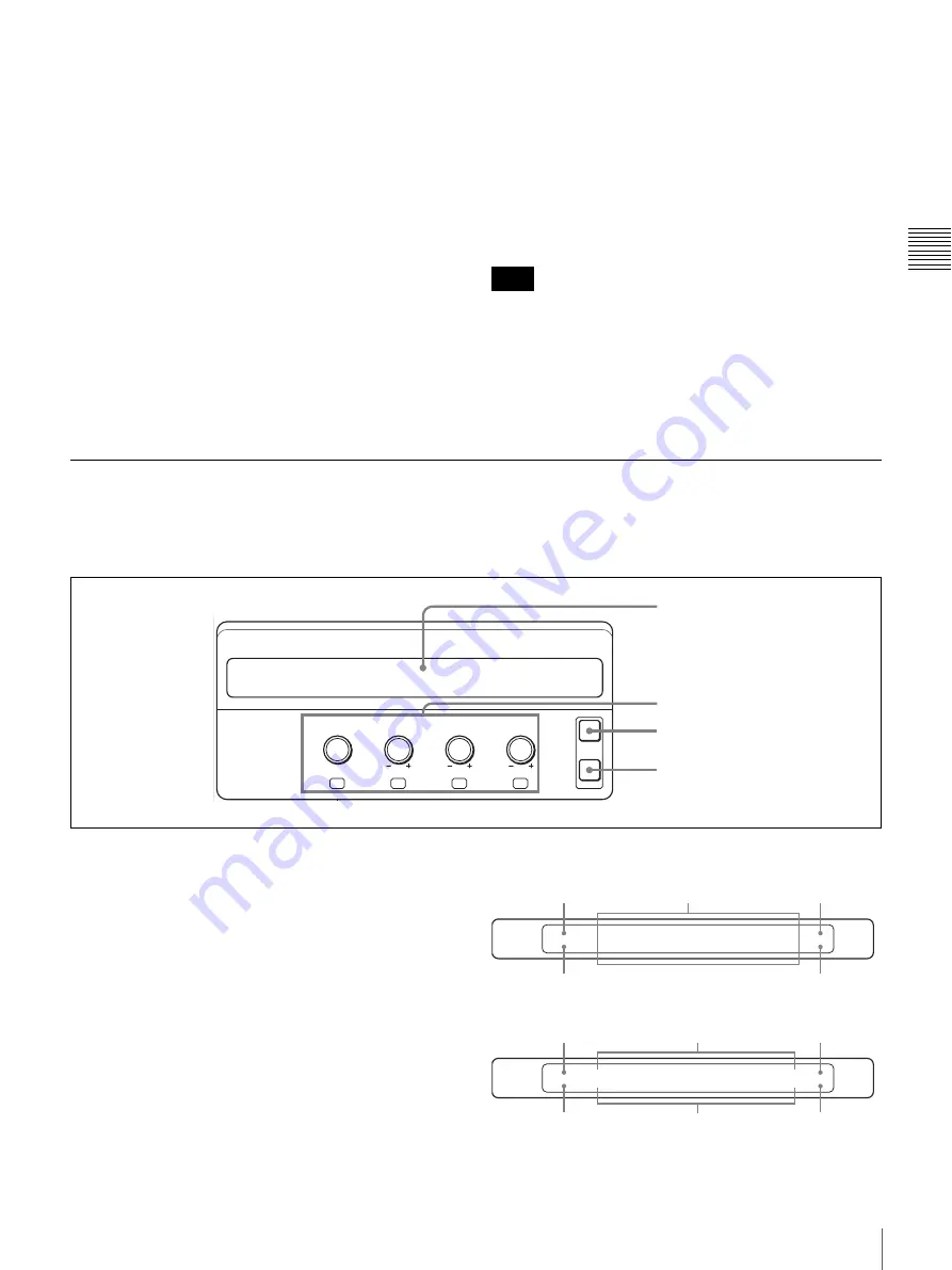
The buttons and controls in this section differ in function
depending on whether the switcher is in CAM mode, in
SW mode or in menu mode.
a
Display panel
Displays the menu, the current effect, and the camera
settings.
While viewing the display panel, you can check and
change the settings.
When the menu of a lower layer has further lower layers,
the menu name is followed by “..”
The following display panel shows a representative
example:
Menu layers in menu mode
Note
NEAR
FAR
EXIT
PAGE
FOCUS
BRIGHT
ZOOM
PAN/TILT
F1
F2
F3
F4
1
Display panel
2
Adjustment controls
3
EXIT button
4
PAGE button
SETUP
INPUT
NAME..
FS..
ASSIGH..
SIDE..
ADJUST..
1/1
920
PROC..
Higher menu layer
Current displayed menu layer
Lower menu layer
Page number
Menu page
INPUT
ADJUST
XPT BTN
3
Y-LEVEL
1.00
SETUP
0.0
3/6
923
C-LEVEL
1.00
Current displayed
menu layer
Menu page
Setting values
Higher menu layer
Setting items
Page number
Содержание BRS-200
Страница 32: ...32 Processor Unit Chapter 2 Locations and Functions of Parts ...
Страница 62: ...62 Basic Setups for the Switcher Chapter 3 Preparations ...
Страница 100: ...100 Storing the Settings of a Wipe PIP and Setting Menu Items Chapter 4 Switching Operation ...
Страница 118: ...118 Setting the Illumination of the Tally Lamp on the Camera Chapter 5 VISCA Camera Operations ...
Страница 130: ...130 Transferring Data between the Switcher and a Computer Chapter 6 Control Using External Devices ...


