background image

RB1G

CHASSIS

W900A/904A/905A

Troubleshooting

Troubleshooting Reference 

Board Name

Board PWB  (B side)

Detail

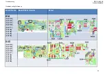
BA2 W

(B id )

BA2-W

(C7348)
(C7349)
(C7350)

(B side)

(

)

C7348

C7350

C7349

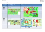
R7386

R7344

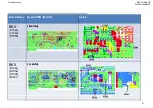
BA2-W

(R7344)
(R7352)
(R7386)

(A side)

R7386

R7344

Pin 1

Pin 7

(R7386)
(CN9101)

CN9101

R7352

Pin 2

28

Содержание BRAVIA KDL-55W900A

Страница 1: ...COMMON SERVICE MANUAL COMMON RB1G CHASSIS Segment HG Version Date Subject 1 4 2013 1st Issue LCD TV 9 888 137 01 For SM Unique please refer 9 888 137 P1 Pan Asia 9 888 137 P1 Pan Asia 9 888 137 C1 China 9 888 137 A1 America 9 888 137 J1 Japan 9 888 137 E1 Europe ...

Страница 2: ...SERVICE MANUAL COMMON SERVICE MANUAL COMMON RB1G CHASSIS Segment HG LCD TV LCD TV ...

Страница 3: ...ON FOR BELOW REGIONS AND MODELS REGION ASIA CHINA AMERICA JAPAN EUROPE MODEL KDL 40W900A KDL 46W900A KDL 55W900A KDL 40W900A KDL 46W900A KDL 55W900A KDL 40W904A KDL 46W904A KDL 55W904A KDL 40W905A KDL 46W905A KDL 55W905A KDL 40W905A KDL 46W905A KDL 55W905A 3 ...

Страница 4: ...set Panel Operation Time 224 4 13 Set to Shipping Condition 224 4 14 Summary of Service Control 224 4 15 Service Menu Tree 225 2 SELF DIAGNOSTIC FUNCTION 2 1 Overview of Control Buttons 16 2 2 LED Display Control 17 2 3 LED Pattern 17 2 4 Standby LED Error Display 17 4 15 Service Menu Tree 225 4 16 How to Enter Self Diagnosis Display 226 4 17 Updating the software 228 4 18 Non network function 228...

Страница 5: ...id causing serious injury Carry the TV with an adequate number of people larger size TVs require two or more people C t h d l t hil i th TV i i t t f 6 Disconnect the AC power when replacing the backlight CCFL or inverter circuit High voltage occurs at the inverter circuit at 650Vrms 7 Always clean the LCD panel with a soft cloth material 8 Use care when handling the wires or connectors of the inv...

Страница 6: ...by means of a VOM or battery operated AC voltmeter The limit indication is 0 75V so analog meters must have an accurate low voltage scale The SIMPSON S 250 and SANWA SH 63TRD are examples of passive VOMs that are suitable Nearly all battery operated digital multimeter that have a 2 VAC range are suitable 3 Check all control knobs shields covers ground straps and mounting hardware have been replace...

Страница 7: ...to 100 watt trouble light not a neon lamp between the hot side of the receptacle and the retaining screw Try both slots if necessary to locate the hot side on the line retaining screw Try both slots if necessary to locate the hot side on the line the lamp should light at normal brilliance if the screw is at ground potential see Figure 3 1 6 Lead Free Information Figure 3 Checking for earth ground ...

Страница 8: ...itions before removing 1 8 Procedure to remove Rear Cover HG 55 1 All screws should be remove on rear cover and AC except stand joint screw 2 Remove stand by pull down as direction then remove joint screw 3 Pull out sound reflector left right AC cover AC cord 4 Remove AC cover plastic Pull out AC cord 5 Forefinger middle finger clutched AC cover hole bottom side 6 The 1st Servicers both hands to p...

Страница 9: ...ick rear cover top side 8 The 2 operator use right hand to pick rear cover top side 9 The two operator put up the rear cover together Notes Caution Point 1 40 Need One Servicer 2 46 55 Need two Servicers 3 Hands need glove 3 Hands need glove 4 Procedure of remove rear cover will be same with all inch 5 Rear cover of bottom side is easy to deform easy to deform Red area is caution Rear cover of bot...

Страница 10: ...side to assemble 3 Check all side whether its properly insert 4 Put reflector left right Alignment Bottom right corner p p y 5 Tighten all screw for rear cover reflector AC cover stand joint screw except four 7 Put stand as direction and tighten j p stand screw 6 Connect AC cord connector install AC cover tighten the screw 7 Put stand as direction and tighten four stand screw 10 ...

Страница 11: ...905A 1 10 Caution Of Rear Cover NG to grab sharp edge and easy to deform sharp edge and easy to deform OK to grab curling area OK to grab ith care OK to grab with care easy to deform area 40 46 55 rear cover will be same sharp edge area 11 ...

Страница 12: ...Pull left side Don t pull right side Pull left side Smart Core Cover Smart Core Cover Recommended disassemble position ORNAMENT Don t pull right side have a hook only right side Lay the display face down on a work surface that is lager than the TV and make space in front of ORNAMENT 2 Take off Harness from Hook have a hook only right side 4 Remove Smart Core from SET a HG MD LK LS MW Model a HG MD...

Страница 13: ...EZEL flame a HG MD LK LS MW Model TE M d l Continue from 4a Scratch marks by Smart Core remain on BEZEL flame TE Model Smart Core Bracket Only TE Wipe marks BACK It moves bottom side with moving on Bracket to back side 5 Release connector harness b TE Model Lock BOTTOM a HG MD LK LS MW TE Model Lock unplug 13 ...

Страница 14: ...e hook by flat plate ex Steel ruler a HG MD LK LS MW TE Model HG MD LK LS MW TE Model Case Pinch and rotate case hook by flat plate ex Steel ruler Lid Put your finger at this position This makes it easy to release hook CASE ORNAMENT 9 Remove HIR PWB 7 Remove Smart Core Lid HG MD LK LS MW TE Model HG MD LK LS MW TE Model LID SC 14 HIR PWB ...

Страница 15: ... HG MD LK LS MW Model Cover Cover Bracket BT PWB common Lid Case HSC PWB WiFi BT Lid Case 11 R l HSC C H k PWB 2 i i d HSC PWB common HIR PWB 11 Release HSC Case Hook PWB 2 position and remove HSC PWB HSC PWB CASE Ornament HG MD LK LS MW TE Model Remove HSC PWB pinching and rotating this hook 15 Remove HSC PWB pinching and rotating this hook ...

Страница 16: ...rol CH Channel Channel 频道 Power Turn the TV on or switch to standby mode INPUT SELECT Volume Press to select the next or previous channel Press to adjust the volume In TV Home Menu buttons will work as Volume Press to select the next or previous channel Press to adjust the volume In TV Home Menu buttons will work as INPUT SELECT Power Turn the TV on or switch to standby mode 频道 频道 USB 2 3 Press to...

Страница 17: ...or AEP CH HK B Board Error LED Driver Error Panel Module T Con Error TCON ERR MD MW HG TE LED Driver Error LD_ERR HG TE Model 4x Off End of Aging mode White Green Blinking Off Blinking 3sec On 3sec Off Software Updating white blinking white blinking off Software Updating finish Off Blue lit off Test Reset White white blinking Off Error of panel ID Off Green Blinking Orange Blinking Blinking 0 5sec...

Страница 18: ...io Skype Can t Work Smart Core no LED Set is still alive Bluetooth One Step Remote OSR can t connect B Board G Board H Board IR H Board SC H Board SC Speaker Skype Module Wifi Module BT Module LD Board LVDS FFC Tcon LCD Panel Problem Power Power LD Panel Tcon Panel Backlight TEMP Soft ware Emitter Audio FAN N A Size B Board Type G Board H H Board Note Details refer to Troubleshooting Section Local...

Страница 19: ...hooting Reference for parts location No Power Check STBY 3 3V L9101 B others C9318 BK G Board Replace Between G Board to B Board Harness NG NG OK Harness OK OK B Board DC DC converter check NO POWER Ayu2 control Size B Board Type G Board Type OTHERS JP 40 BA2 S BA2 W G1A 19 46 BA2 S BA2 W G1A 55 BA2 S BA2 W G1B ...

Страница 20: ...RB1G CHASSIS W900A 904A 905A Troubleshooting Troubleshooting Reference Board Name Board PWB A side Detail BA2 S L9101 L9101 BA2 W L9101 L9101 BM L9101 L9101 20 ...

Страница 21: ...RB1G CHASSIS W900A 904A 905A Troubleshooting Troubleshooting Reference Board Name Board PWB A side Detail BKX BKX C9318 C9318 BKE BKE C9318 C9318 BKJ C9318 C9318 21 ...

Страница 22: ... F9106 no Is the voltage 1V END Check F9105 yes it 1 18V yes Check F9106 Check SL9109 Voltage Is the voltage 5V END Check F9104 no yes Check SL9103 Voltage Is the voltage 3 3V Check F9102 no yes Check SL9107 Voltage Is the voltage 1 5V Check F9102 yes no Size B Board Type G Board Type OTHERS JP 40 BA2 S BA2 W G1A yes 22 46 BA2 S BA2 W G1A 55 BA2 S BA2 W G1B ...

Страница 23: ... PWB A side Detail BA2 S SL9103 SL9105 SL9107 SL9109 F9102 SL9111 SL9105 SL9107 SL9109 SL9111 F9102 F9104 F9104 F9104 F9105 F9106 SL9103 SL9107 F9105 F9106 BA2 W SL9103 SL9105 SL9109 F9102 SL9111 SL9105 SL9107 SL9109 SL9111 F9102 F9104 SL9105 F9104 F9105 F9106 SL9107 SL9103 F9105 F9106 23 ...

Страница 24: ...d PWB A side Detail BM BM SL9103 SL9105 SL9107 SL9109 SL9107 F9104 SL9111 F9106 SL9109 SL9111 F9102 F9104 SL9109 F9105 F9106 F9102 SL9103 F9105 SL9105 BKE SL9103 SL9105 SL9107 SL9109 SL9103 F9102 F9105 SL9107 SL9109 SL9111 F9102 F9104 SL9111 SL9105 F9104 F9105 F9106 F9104 SL9107 F9106 24 ...

Страница 25: ...ame Board PWB A side Detail BKX SL9103 SL9105 SL9107 SL9109 SL9103 F9102 F9105 SL9107 SL9109 SL9111 F9102 F9104 F9105 F9104 F9105 F9106 F9104 SL9107 SL9111 BKJ SL9103 SL9105 SL9109 SL9103 F9102 SL9105 SL9107 SL9109 SL9111 F9102 F9105 F9102 F9104 F9105 F9106 F9104 SL9107 SL9111 25 ...

Страница 26: ...k for where OK NG _ at CN9101 pin1 except BK or replace AYU2 at AYU2 A9 pin R7344 OK K5 L5 L10 J7 pin C7349 STBY_ 1 8V is NG OK Check STBY_ 1 0V at AYU2 N13 P13 pin C7350 look for where STBY_ 1 0V is NG G board Adapter LW NG Check REG 12V at CN9101 pin7 Check REG 19V 9301 NG Check Xtal oscillation OK NG It might be power supply problem at F9301 BK only OK Size B Board Type G Board Type OTHERS JP 4...

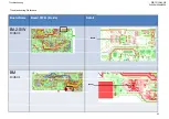
Страница 27: ... 904A 905A Troubleshooting Troubleshooting Reference Board Name Board PWB Detail BA2 S C7348 C7349 C7350 B side C7349 C7350 C7348 C7350 BA2 S R7344 R7352 A side R7386 R7344 Pin 1 Pin 7 R7386 CN9101 CN9101 Pin 2 27 R7352 ...

Страница 28: ...bleshooting Troubleshooting Reference Board Name Board PWB B side Detail BA2 W B id BA2 W C7348 C7349 C7350 B side C7348 C7350 C7349 R7386 R7344 BA2 W R7344 R7352 R7386 A side R7386 R7344 Pin 1 Pin 7 R7386 CN9101 CN9101 R7352 Pin 2 28 ...

Страница 29: ...A 905A Troubleshooting Troubleshooting Reference Board Name Board PWB B side Detail BM B id BM C7348 C7349 C7350 B side C7348 C7350 C7349 BM R7344 R7352 R7386 A side R7344 R7386 R7386 CN9101 CN9101 Pin 7 R7352 Pin 1 Pin 2 29 ...

Страница 30: ...00A 904A 905A Troubleshooting Troubleshooting Reference Board Name Board PWB B side Detail BKE B side C7349 BKE C7348 C7349 C7350 B side C7348 C7350 BKE R7344 R7352 R7386 A side R7352 R7386 F9301 R7344 R7386 F9301 30 ...

Страница 31: ...CHASSIS W900A 904A 905A Troubleshooting Board Name Board PWB B side Detail BKX C7348 C7349 C7350 B side C7349 C7350 C7348 C7350 C7348 BKX R7344 R7352 A side C7350 R7352 R7352 R7386 F9301 F9301 31 R7344 R7386 ...

Страница 32: ...CHASSIS W900A 904A 905A Troubleshooting Board Name Board PWB B side Detail C7349 BKJ C7348 C7349 C7350 B side C7349 C7350 C7348 C7350 BKJ R7344 R7352 A side C7350 R7352 R7386 F9301 F9301 R7386 32 R7344 R7386 ...

Страница 33: ... fail No Store SW log Check SW behaviors AYU2 power is OK Yes Check DDR RawNAND interface device failure Data fails are especially in environment area If thi A h DDR device fail Erase RawNAND From the error message we can find which device has failure Software was written Yes No If this Area has broken check soft cannot run In this case corrupted data are written to NAND flash in proper Erase RawN...

Страница 34: ...replacement flow Product SW rewrite Recover Product SW iti i Yes Recover SW writing issue No RawNAND erase AYU2 replacement Product SW write RawNAND replacement Product SW write Recover No Product SW write Recover AYU2 issue RawNAND issue Yes Yes No Note 34 Board issue No Note AYU2 IC9000 Brownie IC9001 ...

Страница 35: ...obe CL2205 CL2206 I2C bus dumping or AYU2 Brownie OK Check 3 3V_MAIN_1 at JL9116 on the B Board F9102 IC9102 etc B Board Check AUDIO 12 5V at pin 8 10 of G Board NG NG OK SPIC check Probe RB8522 SPI dumping resistor or AYU2 CN9101 on the B Board G Board Check 12 5V OK OK OK I2C_CCP check R8502 and R8503 I2C_CCP Pull U Check 1 8V_MAIN on IC9201 etc NG Check 12 5V at Power Amp side of F4601 on the B...

Страница 36: ...RB1G CHASSIS W900A 904A 905A Troubleshooting Troubleshooting Reference Board Name Board PWB A side Detail BA2 S W CL2151 CL2152 CL2152 CL2151 BM CL2151 CL2151 CL2152 CL2152 CL2151 36 ...

Страница 37: ...RB1G CHASSIS W900A 904A 905A Troubleshooting Troubleshooting Reference Board Name Board PWB A side Detail BKX J CL2151 CL2152 CL2152 BKT BKE CL2151 CL2151 CL2152 CL2151 CL2152 37 ...

Страница 38: ...RB1G CHASSIS W900A 904A 905A Troubleshooting Troubleshooting Reference Board Name Board PWB A side Detail BA2 S W R8502 R8503 R8502 R8503 BM R8502 R8503 R8502 R8503 38 ...

Страница 39: ...RB1G CHASSIS W900A 904A 905A Troubleshooting Troubleshooting Reference Board Name Board PWB A side Detail BKX J R8502 R8503 R8503 BKE R8502 R8502 R8503 R8503 R8502 39 ...

Страница 40: ...RB1G CHASSIS W900A 904A 905A Troubleshooting Troubleshooting Reference Board Name Board PWB A side Detail BA2 S W CL5023 CL5024 CL5023 CL5024 BM CL5024 BM CL5023 CL5024 CL5023 CL5024 40 ...

Страница 41: ...RB1G CHASSIS W900A 904A 905A Troubleshooting Troubleshooting Reference Board Name Board PWB A side Detail BKX J CL5023 CL5024 CL5024 CL5024 CL5023 BKE CL5023 CL5024 CL5024 CL5023 41 ...

Страница 42: ...RB1G CHASSIS W900A 904A 905A Troubleshooting Troubleshooting Reference Board Name Board PWB A side Detail BA2 S W CN9101 CN9101 CN9101 pin9 CN9101 pin8 BM CN9101 CN9101 pin9 CN9101 pin8 42 ...

Страница 43: ...RB1G CHASSIS W900A 904A 905A Troubleshooting Troubleshooting Reference Board Name Board PWB B side Detail BA2 S W IC4601 IC4601 BM IC4601 IC4601 43 ...

Страница 44: ...RB1G CHASSIS W900A 904A 905A Troubleshooting Troubleshooting Reference Board Name Board PWB A side Detail BKX J IC4601 F4601 F4601 BKE IC4601 IC4601 IC4601 F4601 F4601 IC4601 44 ...

Страница 45: ...RB1G CHASSIS W900A 904A 905A Troubleshooting Troubleshooting Reference Board Name Board PWB B side Detail BA2 S W F4601 F4601 BM F4601 F4601 45 ...

Страница 46: ...1 Out pin 9 16 25 32 Switching 0V to 12V No Check the IC4601 pin 18 at CL4606 is HIGH No impedance Low impedance IC4601 or parts around IC4601 NG around 300 400kHz Yes Yes Solder NG IC4601 Check broken parts IC4601 or parts around IC4601 NG Check the CN4601 DC level 2V at No L4601 L4604 or C4611 C4614 No burn or broken Yes around IC4601 JL4621 JL4624 C4611 C4614 NG Yes Check the IC4601 I2S line pi...

Страница 47: ...RB1G CHASSIS W900A 904A 905A Troubleshooting BA2 board Side A Troubleshooting Reference BA2 board Side A C C C CL4602 CL4603 CL4604 CL4601 47 ...

Страница 48: ...RB1G CHASSIS W900A 904A 905A Troubleshooting BA2 board Side B Troubleshooting Reference BA2 board Side B IC4601 F4601 9 16 25 32 CL4606 JL462 JL462 JL462 JL462 48 21 2 23 24 ...

Страница 49: ...Troubleshooting Troubleshooting Reference BM board Side B not applicable for this model BM board Side B not applicable for this model F4601 CL4606 9 16 25 32 CL460 CL460 CL460 CL460 IC4601 JL4621 JL4622 JL4623 02 01 03 04 49 JL4624 ...

Страница 50: ... enough Check the IC4601 Out pin 38 42 43 47 Switching 0V to 19V No Check the IC4601 pin 18 at CL4606 is HIGH No impedance Low impedance IC4601 or parts around IC4601 NG around 300 400kHz Yes Yes Solder NG IC4601 Check broken parts IC4601 or parts around IC4601 NG Check the CN4601 DC level 9 7V No L4601 L4604 or C4611 C4614 No burn or broken Yes around IC4601 at JL4621 JL4624 C 6 C 6 NG Yes Check ...

Страница 51: ...905A Troubleshooting Troubleshooting Reference BKE and BKX board Side A Not applicable for this model BKE and BKX board Side A Not applicable for this model CL46 CL46 CL46 F4601 602 604 603 IC4601 CL4601 IC4601 32 42 43 47 51 ...

Страница 52: ...CHASSIS W900A 904A 905A Troubleshooting Troubleshooting Reference BKE and BKX board Side B Not applicable for this model BKE and BKX board Side B Not applicable for this model JL4621 JL4622 JL4624 JL4622 52 ...

Страница 53: ...8001 on on the B Board G Board Panel T con About 12 5V NG OK Symptom improvement Confirm Tcon12V Check JL9112 BACKLIGHT_MON on the B Board LED driver Between 0 98V to 1 23V Replace the Harness Between G and Panel Harness Symptom improvement B Board Replace the LVDS Harness LVDS Harness Symptom improvement NG NG For Ayu2 IC9000 replacement check related section Size B Board Type G Board Type OTHERS...

Страница 54: ...RB1G CHASSIS W900A 904A 905A Troubleshooting Troubleshooting Reference BA2 board Side B BA2 board Side B BACKLIGHT_MON JL9112 LED Blinking 4x LED Voltage Error 54 ...

Страница 55: ...W900A 904A 905A Troubleshooting Troubleshooting Reference BK board Side B Not applicable for this model BK board Side B Not applicable for this model LED Blinking 4x LED Voltage Error BACKLIGHT_MON JL8206 JL8206 55 ...

Страница 56: ...0A 904A 905A Troubleshooting Troubleshooting Reference BM board Side B not applicable for this model BM board Side B not applicable for this model BACKLIGHT MON LED Blinking 4x LED Voltage Error BACKLIGHT_MON JL9112 56 ...

Страница 57: ...RB1G CHASSIS W900A 904A 905A Troubleshooting Troubleshooting Reference BA2S board Side A BA2S board Side A LED Blinking 5x T Con Error HG and TE Model PANEL_VCC 57 ...

Страница 58: ...SIS W900A 904A 905A Troubleshooting Troubleshooting Reference BK board Side A Not applicable for this model BK board Side A Not applicable for this model LED Blinking 5x T Con Error HG and TE Model PANEL_VCC 58 ...

Страница 59: ...SIS W900A 904A 905A Troubleshooting Troubleshooting Reference BM board Side A Not applicable for this model BM board Side A Not applicable for this model LED Blinking 5x T Con Error HG and TE Model PANEL_VCC 59 ...

Страница 60: ...tilation etc Set to another location etc NG JL9112 at Pin 18 of CN9101 on the B Board B Board Low High For Ayu2 IC9000 replacement check related section Yes Panel NG Change B Board and Aging a few hours G board Adapter BK only Symptom improvement Change G Board Symptom improvement NG Panel B Board Size B Board Type G Board Size B Board Type G Board Type OTHERS JP 40 BA2 S BA2 W G1A 46 BA2 S BA2 W ...

Страница 61: ... blinking g No B Board NG CH or AEP destination o YES Using CAM Module YES No B Board NG YES Check clock signal pin AM30 of IC9000 AYU2 NG CI CAM module B Board NG B Board NG OK Size B Board Type G Board Type OTHERS JP 40 BA2 S BA2 W G1A 61 B Board NG 46 BA2 S BA2 W G1A 55 BA2 S BA2 W G1B ...

Страница 62: ...RB1G CHASSIS W900A 904A 905A Troubleshooting Troubleshooting Reference Board Name Board PWB B side Detail BA2 S W R8558 R8558 BM R8558 R8558 R8558 62 ...

Страница 63: ...RB1G CHASSIS W900A 904A 905A Troubleshooting Troubleshooting Reference Board Name Board PWB A side Detail BKJ R8558 R8558 R8558 BKE R8558 R8558 63 ...

Страница 64: ... TV Speaker TV Speakers Change the Speaker Harness Replace the B Board NG Symptom improvement No Sound Audio B Board Speaker Harness Speaker NG Symptom improvement No Sound Tuner No Sound HDMI Speaker Harness Speaker Size B Board Type G Board Type OTHERS JP 40 BA2 S BA2 W G1A 64 46 BA2 S BA2 W G1A 55 BA2 S BA2 W G1B ...

Страница 65: ...OK NG IC4501 NG CN4801 is NG Check the Speaker Sound use Video input Power Amp Block F4601 IC4601 etc is NG See item LED blinking 3x OK Solder NG Check the HP out NG OK OK Check the X_AUDIO_MUTE_ SPHPLO pin5 is HIGH p is NG See item LED blinking 3x Audio error NO This is MUTE situation Check IC9000 Check the HP out use Video input OK No Problem NG Check the INR INL pin1 14 at CL4502 and CL4501 IC9...

Страница 66: ...RB1G CHASSIS W900A 904A 905A Troubleshooting Troubleshooting Reference BA2 board Side B BA2 board Side B CN4801 Vin pin Vcc 66 1 ...

Страница 67: ...00A 904A 905A Troubleshooting Troubleshooting Reference BA2 board Side B BA2 board Side B CL4602 CL4603 CL4604 CL460 2 3 4 CL4502 CL4501 01 INR 1 14 IN 9 Vdd X_AUDIO_MUTE_SPHPLO 5 Vss 6 CP 7 8 CN IC4501 C4501 67 C4501 ...

Страница 68: ...Troubleshooting Troubleshooting Reference BM board Side A not applicable for this model BM board Side A not applicable for this model 9 Vdd 8 CN 14 IN CL4501 IC4501 6 7 1 CL4502 5 Vss CP INR C4501 CL4502 MUTE_SPHPLO 5 X_AUDIO_M 68 ...

Страница 69: ...RB1G CHASSIS W900A 904A 905A Troubleshooting Troubleshooting Reference BM board Side B not applicable for this model BM board Side B not applicable for this model CN4801 Vin pin Vcc 69 n 1 ...

Страница 70: ...RB1G CHASSIS W900A 904A 905A Troubleshooting Troubleshooting Reference BKE and BKX board Side A Not applicable for this model BKE and BKX board Side A Not applicable for this model C4501 70 ...

Страница 71: ...B1G CHASSIS W900A 904A 905A Troubleshooting Troubleshooting Reference BKE and BKX board Side B Not applicable for this model BKE and BKX board Side B Not applicable for this model CN4801 Vin pin 1 Vcc 71 ...

Страница 72: ...Troubleshooting Troubleshooting Reference BKE and BKX board Side B Not applicable for this model BKE and BKX board Side B Not applicable for this model CL4501 CL4502 IC4501 1 INR IN 14 Vdd 9 5 X_AUDIO_MUTE_SPHPLO 6 Vss 7 CP CN 8 72 ...

Страница 73: ...C9000 OK Check the IC4511 pin 3 VCC 3 3V DC DC converter is NG See to section 3 1 2 No POWER Ayu2 Control NG IC9001 is NG No signal INR INL pin10 1 IC4511 at CL4512 and CL4511 Signal is coming OK NG IC4511 NG OK Check the Signal is coming Check the solder OK NG NG OK IC4511 pin 6 VEE 3 3V Of IC4511 CP CN 4 5pin C4511 Size B Board Type G Board Type OTHERS JP 40 BA2 S BA2 W G1A N t IC4511 NG OK Sold...

Страница 74: ...RB1G CHASSIS W900A 904A 905A Troubleshooting Troubleshooting Reference BA2 board Side B BA2 board Side B CL4512 CL4511 3 Vcc 3 3V Vee 3 3V 6 4 CP 5 CN C4511 CNT 7 1 INL INR 10 74 ...

Страница 75: ...A Troubleshooting Troubleshooting Reference BKE and BKX board Side A Not applicable for this model BKE and BKX board Side A Not applicable for this model Ve CL4512 ee 3 3V 6 CNT 7 INR 10 3 Vcc 3 3V 4 CP 5 CN 1 INL CL4511 75 C4511 ...

Страница 76: ... GND C4607 GND C4608 GND C4609 GND 3 Check connectivity audio 3 3V_MAIN to GND only for BKE and BKX board IC4601 Pin8 GND IC4601 Pin27 GND No short to GND Either 1 short to GND 4 Check connectivity audio output to GND CN4601 Pin 1 GND Pin 2 GND No short to GND Either 1 of pin short to GND Pin 2 GND Pin 3 GND Pin 4 GND Size B Board Type G Board Type OTHERS JP 40 BA2 S BA2 W G1A N t 76 46 BA2 S BA2 ...

Страница 77: ...RB1G CHASSIS W900A 904A 905A Troubleshooting Troubleshooting Reference BA2 board Side A BA2 board Side A Pin Pin Pin Pin 1 2 3 4 CN4601 CN4601 77 ...

Страница 78: ...RB1G CHASSIS W900A 904A 905A Troubleshooting Troubleshooting Reference BA2 board Side B BA2 board Side B IC4601 F4601 C4608 C4609 C4606 C4607 78 ...

Страница 79: ...RB1G CHASSIS W900A 904A 905A Troubleshooting Troubleshooting Reference BM board Side A not applicable for this model BM board Side A not applicable for this model CN4601 Pin 4 Pin 3 Pin 2 Pin 1 79 ...

Страница 80: ...RB1G CHASSIS W900A 904A 905A Troubleshooting Troubleshooting Reference BM board Side B not applicable for this model BM board Side B not applicable for this model F4601 C4607 C4606 IC4601 C4608 C4609 80 ...

Страница 81: ...bleshooting Troubleshooting Reference BKE and BKX board Side A Not applicable for this model BKE and BKX board Side A Not applicable for this model F4601 8 IC4601 8 2 CN4601 C4606 C4609 2 7 Pin 4 Pin 3 Pin 2 Pin 1 81 C4607 C4608 C 609 ...

Страница 82: ... CN4601 Pi 3 Must have good connection 0 Ω Open circuit L4603 near to IC side CN4601 Pin3 L4604 near to IC side CN4601 Pin4 6 Check connectivity audio output path only for BKE and BKX board Must have good connection 0 Ω Open circuit y L4601 near to IC side CN4601 Pin4 L4602 near to IC side CN4601 Pin3 L4603 near to IC side CN4601 Pin2 L4604 near to IC side CN4601 Pin1 Size B Board Type G Board Typ...

Страница 83: ...RB1G CHASSIS W900A 904A 905A Troubleshooting BA2 board Side A Troubleshooting Reference CN4601 P P P P Pin 1 Pin 2 Pin 3 Pin 4 L4602 L4601 L4603 L4604 83 ...

Страница 84: ...SIS W900A 904A 905A Troubleshooting Troubleshooting Reference BM board Side A not applicable for this model BM board Side A not applicable for this model L4601 L4602 L4604 L4603 CN4601 Pin 4 Pin 3 Pin 2 Pin 1 84 ...

Страница 85: ...905A Troubleshooting Troubleshooting Reference BKE and BKX board Side A Not applicable for this model BKE and BKX board Side A Not applicable for this model F4601 L4601 L4602 L4603 L4604 L4604 CN4601 Pin 4 Pin 3 Pin 2 Pin 1 85 ...

Страница 86: ...d only V before fuse 12 5V 0 5V V after fuse 12 5V 0 5 V No voltage Check fuse broken Check CN9101 Pin 8 10 got 12 5V Change fuse 5A Check power supply board audio VCC 3 Check F4601 MainSP for BKE and BKX V before fuse 19 5V 0 5V V after fuse 19 5V 0 5 V No voltage Change fuse 5A Check power supply board only p pp y board audio VCC 4 Check IC4601 Pin 8 and C4601 Pin 27 for BKE and BKX board only V...

Страница 87: ...RB1G CHASSIS W900A 904A 905A Troubleshooting Troubleshooting Reference BA2 board Side A L4602 L4601 L4603 L4604 87 ...

Страница 88: ...RB1G CHASSIS W900A 904A 905A Troubleshooting Troubleshooting Reference BA2 board Side A BA2 board Side A CN9101 Pin Pi n 8 n 10 88 ...

Страница 89: ...RB1G CHASSIS W900A 904A 905A Troubleshooting Troubleshooting Reference BA2 board Side B F4601 89 ...

Страница 90: ...ASSIS W900A 904A 905A Troubleshooting Troubleshooting Reference BM board Side A not applicable for this model BM board Side A not applicable for this model CN9101 Pin 8 Pin 10 L4601 L4602 L4604 L4603 90 L4603 ...

Страница 91: ...RB1G CHASSIS W900A 904A 905A Troubleshooting Troubleshooting Reference BM board Side B not applicable for this model BM board Side B not applicable for this model F4601 91 ...

Страница 92: ... W900A 904A 905A Troubleshooting Troubleshooting Reference BKE and BKX board Side A Not applicable for this model BKE and BKX board Side A Not applicable for this model F4601 L4601 L4602 L4603 L4604 L4603 L4604 92 ...

Страница 93: ... 904A 905A Troubleshooting Troubleshooting Reference BKE and BKX board Side A Not applicable for this model BKE and BKX board Side A Not applicable for this model F4601 8 IC4601 8 2 CN4601 2 7 Pin 4 Pin 3 Pin 2 Pin 1 93 ...

Страница 94: ...NG Check IC9000 6 Check CL4601 CL4602 CL4603 CL4604 CL4601 12 288MHz CL4603 3 072MHz CL4604 48KHz CL4602 moving CLK If no frequency at CL4601 CL4603 CL4604 Ayu2 IC IC9000 NG If no frequency at CL4602 If sound source OK but CL4602 NG Ayu2 IC IC9000 NG All Vp p 3 3V make sure sound source OK Size B Board Type G Board Type OTHERS JP 40 BA2 S BA2 W G1A 94 46 BA2 S BA2 W G1A 55 BA2 S BA2 W G1B Note AYU...

Страница 95: ...RB1G CHASSIS W900A 904A 905A Troubleshooting Troubleshooting Reference BA2 board Side A BA2 board Side A C C C CL4602 CL4603 CL4604 CL4601 95 ...

Страница 96: ...RB1G CHASSIS W900A 904A 905A Troubleshooting Troubleshooting Reference BA2 board Side B CL4607 96 CL4605 CL4606 ...

Страница 97: ...RB1G CHASSIS W900A 904A 905A Troubleshooting Troubleshooting Reference BM board Side B not applicable for this model pp CL4606 CL CL CL CL CL4605 IC4601 CL4606 L4602 L4601 L4603 L4604 CL4607 97 ...

Страница 98: ...A Troubleshooting Troubleshooting Reference BKE and BKX board Side A Not applicable for this model BKE and BKX board Side A Not applicable for this model CL46 CL46 CL46 CL46 CL46 F4601 602 604 603 605 607 IC4601 CL4601 CL4601 98 ...

Страница 99: ...RB1G CHASSIS W900A 904A 905A Troubleshooting Troubleshooting Reference BKE and BKX board Side B Not applicable for this model BKE and BKX board Side B Not applicable for this model CL4606 99 ...

Страница 100: ...sert HP Jack Check R4508 Vdc 3 3V 0 3V Vdc 0V or 1V Check HP_DET line R8113 for BA2 and BM R8124 for BKE and BKX got R8124 for BKE and BKX got short to GND 2 Check IC4501 Pin 5 X AUDIO MUTE SPHPLO Vdc 3 3V 0 3V Vdc 0V or 1V Check X_AUDIO_ MUTE1_ SPHLO Pin 5 short to GND _ _ _ 3 Check CL4505 CL4506 with audio signal input Can see audio signal waveform Cannot see audio signal waveform Go to below it...

Страница 101: ...RB1G CHASSIS W900A 904A 905A Troubleshooting Troubleshooting Reference BA2 Board Side A BA2 Board Side A CL4505 CL4506 C 505 R4508 101 ...

Страница 102: ...RB1G CHASSIS W900A 904A 905A Troubleshooting Troubleshooting Reference BA2 Board Side B BA2 Board Side B CL4602 CL4603 CL4604 CL4502 CL4501 CL4601 9 Vdd X_AUDIO_MUTE_SPHPLO 5 IC4501 C4501 R8113 102 ...

Страница 103: ...904A 905A Troubleshooting Troubleshooting Reference BM board Side A not applicable for this model BM board Side A not applicable for this model 9 Vdd CL4501 CL4505 IC4501 O 5 CL4502 CL4506 MUTE_SPHPLO R4508 X_AUDIO_M 103 ...

Страница 104: ...RB1G CHASSIS W900A 904A 905A Troubleshooting Troubleshooting Reference BM board Side B not applicable for this model BM board Side B not applicable for this model R8113 R8113 104 ...

Страница 105: ...900A 904A 905A Troubleshooting Troubleshooting Reference BKE and BKX board Side A Not applicable for this model BKE and BKX board Side A Not applicable for this model CL4506 R4508 CL4506 CL4505 R4508 C4501 R8124 105 ...

Страница 106: ...904A 905A Troubleshooting Troubleshooting Reference BKE and BKX board Side B Not applicable for this model BKE and BKX board Side B Not applicable for this model CL4502 CL4501 CL4502 IC4501 Vdd 9 5 X_AUDIO_MUTE_SPHPLO 106 ...

Страница 107: ...form Cannot see audio signal waveform Go to checking 3 3 2 NO SOUND Audio with audio signal input Digital RF mode waveform waveform 3 3 2 NO SOUND Audio Additional For Europe models only 2 Check IC4511 pin3 Vdc 3 3V 0 3V No 3 3V supply 3 Ch k CL4511 CL4512 C i t di i l C t di i l B i IC IC9001 NG Size B Board Type G Board 3 Check CL4511 CL4512 with audio signal input Digital RF mode Can see input ...

Страница 108: ...RB1G CHASSIS W900A 904A 905A Troubleshooting Troubleshooting Reference BA2 board Side B CL4512 CL4511 3 Vcc 3 3V CL4516 CL4515 108 ...

Страница 109: ...S W900A 904A 905A Troubleshooting Troubleshooting Reference BKE and BKX board Side A Not applicable for this model BKE and BKX board Side A Not applicable for this model CL4512 CL4515 3 Vcc 3 3V CL4511 CL4515 109 ...

Страница 110: ...SIS W900A 904A 905A Troubleshooting 3 3 7 NO SOUND TUNER This troubleshooting is only for Analog No Sound with normal picture NO Y Only RF tuner input NO Please refer audio troubleshooting Check Brownie Yes 110 ...

Страница 111: ... to HDMI DVI HDMI Change HDMI DVI Audio Source to Auto PC Audio What is set in HDMI DVI Audio Source of Sound MENU Replace IC9000 to Auto Does this model have D sub input Yes No Auto or HDMI Audio OK Check R5071 C5071 C5072 C5059 C5073 OK NG Replace NG part Check Sound by other TV set which is same model No Check Source equipment by Reference TV set C5059 C5073 Is Distributor used NO which is same...

Страница 112: ...NG part Check Sound by other TV set which is same model NG OK Check Source equipment Size B Board Type G Board Type Inform the designer of it OK by Reference TV set For example Samsung TV UN46ES7000 Toshiba TV 42WL863 or VA 1836 Type OTHERS JP 40 BA2 S BA2 W G1A 46 BA2 S BA2 W G1A NG Check the settings of S i t Note AYU2 IC9000 112 55 BA2 S BA2 W G1B Source equipment AYU2 IC9000 Brownie IC9001 ...

Страница 113: ...RB1G CHASSIS W900A 904A 905A Troubleshooting Troubleshooting Reference BA2 board Side B BA2 board Side B C5059 R5071 C5071 C5073 C5072 BA2 BA2 B Side B Side 113 C5072 BA2 BA2 B Side B Side ...

Страница 114: ...IS W900A 904A 905A Troubleshooting BM board Side B not applicable for this model Troubleshooting Reference BM board Side B not applicable for this model R5071 BM BM B Side B Side C5071 C5072 C5059 C5073 C5059 114 ...

Страница 115: ...RB1G CHASSIS W900A 904A 905A Troubleshooting Troubleshooting Reference BKE board Side B Not applicable for this model pp BKE BKE B Side B Side C5059 C5073 C5059 C5071 C5072 C5071 R5071 115 ...

Страница 116: ...RB1G CHASSIS W900A 904A 905A Troubleshooting Troubleshooting Reference BKX board Side B Not applicable for this model BKX BKX B Side B Side C5073 C5059 C5072 C5071 R5071 116 ...

Страница 117: ...RB1G CHASSIS W900A 904A 905A Troubleshooting Troubleshooting Reference BKJ board Side B Not applicable for this model pp BKJ BKJ B Side B Side C5073 C5059 C5071 C5072 R5071 117 ...

Страница 118: ...RB1G CHASSIS W900A 904A 905A Troubleshooting 3 4 RB1 Analog Signal Path 118 ...

Страница 119: ...6 and IC9001 No 20 signal path Detailed SDIF path Check between IC9001 and IC9000 OK and IC9001 J3104 signal path Confirm HDMI input working OK C3120 and IC9001 J3104 signal path Detailed SDIF path Check between IC9001 and IC9000 OK and IC9001 11 15 signal path Detailed SDIF path Check between IC9001 and IC9000 NG OK Confirm Analog RF input working NG Check signal between IC9001 and IC9000 R8633 O...

Страница 120: ...CHASSIS W900A 904A 905A Troubleshooting Troubleshooting Reference BA2 S Board SIDE A AEP BA2 S Board SIDE A AEP J3104 CN3101 R8627 RB5008 BA2 S AEP A SIDE 120 C3106 C3109 C3108 C3107 C3120 C3121 C3122 C3123 ...

Страница 121: ...RB1G CHASSIS W900A 904A 905A Troubleshooting Troubleshooting Reference BA2 S Board SIDE B AEP BA2 S Board SIDE B AEP C8017 C8017 C7020 BA2 S AEP B SIDE R3118 121 ...

Страница 122: ...IS W900A 904A 905A Troubleshooting Troubleshooting Reference BKE Board SIDE A Not applicable for this model BKE A SIDE pp C3106 C3109 C3108 C3107 C3120 C3120 C3121 C3122 C3123 RB5008 C8017 CN3101 R8627 122 J3104 ...

Страница 123: ...1G CHASSIS W900A 904A 905A Troubleshooting Troubleshooting Reference BKE Board SIDE A Not applicable for this model BKX Board SIDE B Not applicable for this model pp BKE A SIDE BKX B SIDE 123 R3118 C7010 ...

Страница 124: ...N3102 signal path Pin 1 pin 2 pin 3 NG Check wave between C3126 C3127 C3128 and IC9001 OK Detailed TMDS path NG p check between IC9001 and IC5009 Confirm other analog NG Check signal between IC9001 and NG HDMI EQ IC5009 Problem NG Confirm HDMI input working Si B B d T G B d Input working Ayu2 IC9000 Problem OK IC5009 RB5008 Brownie IC9001 Problem OK Note Size B Board Type G Board Type OTHERS JP 40...

Страница 125: ...RB1G CHASSIS W900A 904A 905A Troubleshooting Troubleshooting Reference BA2S Board AEP B2B Side A Not applicable for this model pp CN3102 R3150 R3149 RB5008 BA2S AEP B2B A SIDE 125 C3128 C3127 C3126 ...

Страница 126: ...RB1G CHASSIS W900A 904A 905A Troubleshooting Troubleshooting Reference BA2S Board AEP B2B Side B not applicable for this model pp C7012 BA2S AEP B2B B SIDE 126 ...

Страница 127: ... Between C3120 C3121 and IC9001 Detailed check J3104 signal path NG OK CR_DET Check wave between C3120 and IC9001 Detailed check J3104 signal path NG VIDEOB_DET OK OK HDMI EQ IC5009 Problem NG OK NG Detailed SDIF path Check between IC9001 and IC9000 OK Confirm HDMI input working OK OK NG Detailed SDIF path Check between IC9001 and IC9000 NG OK Confirm Analog RF input working Check signal between I...

Страница 128: ...RB1G CHASSIS W900A 904A 905A Troubleshooting Troubleshooting Reference BA2S Board PA Side A J3104 J3104 J3101 R8627 RB5008 BA2S PA A SIDE 6 0 1 2 3 128 C3106 C3120 C3121 C3122 C3123 ...

Страница 129: ...RB1G CHASSIS W900A 904A 905A Troubleshooting Troubleshooting Reference BA2S Board PA Side B C8017 C7010 C7008 BA2S PA B SIDE 129 ...

Страница 130: ...RB1G CHASSIS W900A 904A 905A Troubleshooting Troubleshooting Reference BM Board Side A Not applicable for this model pp BM A SIDE R8627 C3106 C3120 C3121 RB5008 130 J3104 J3101 ...

Страница 131: ...RB1G CHASSIS W900A 904A 905A Troubleshooting Troubleshooting Reference BM Board Side B Not applicable for this model pp BM B SIDE C7008 C7010 C8017 131 ...

Страница 132: ...RB1G CHASSIS W900A 904A 905A Troubleshooting Troubleshooting Reference BKX Board Side A Not applicable for this model pp BKX A SIDE C3106 C3120 C3121 C3122 C3123 J3101 RB5008 C8017 R8627 132 J3104 ...

Страница 133: ...RB1G CHASSIS W900A 904A 905A Troubleshooting Troubleshooting Reference BKX Board Side B Not applicable for this model BKX Board Side B Not applicable for this model C7008 C7010 133 ...

Страница 134: ... wave between C3106 and IC9001 Detailed check J3101 signal path NG VIDEOA_DET OK Check wave Between C3120 C3121 and IC9001 Detailed check TB3101 signal path NG OK _ OK HDMI EQ IC5009 Problem NG OK NG Detailed SDIF path Check between IC9001 and IC9000 OK Confirm HDMI input working OK NG OK Confirm Analog RF input working Check signal between IC9001 and IC9000 R8633 Ayu2 IC9000 OK Detailed TMDS path...

Страница 135: ...RB1G CHASSIS W900A 904A 905A Troubleshooting Troubleshooting Reference BA2W A SIDE JP BA2W A SIDE JP TB3101 TB3101 J3101 R8627 RB5008 BA2 W JP A SIDE 135 C3106 C3120 C3121 C3122 C3123 ...

Страница 136: ...RB1G CHASSIS W900A 904A 905A Troubleshooting Troubleshooting Reference BA2W B SIDE JP BA2W B SIDE JP C7010 C7008 C7008 BA2 W JP B SIDE 136 ...

Страница 137: ...rrectly RF Level Low RF Level Low RF Level High Confirm Power supply for RF input circuit A2 5V LNA_5V Confirm AGC1 IC2151 Pin6 AGC 0 AGC 0 L Check Power supply circuit NG Input signal is too big Insert Attenuator Check M t condition in AGC1 line Confirm tuner control line TU_SCL TU_SDA A_RESET Confirm IF1 line H OK OK Check M t condition in tuner control line Check M t condition NG NG Si B B d T ...

Страница 138: ...RB1G CHASSIS W900A 904A 905A Troubleshooting Troubleshooting Reference BA2S IC2151 PIN 6 IC2151 PIN 6 IC9001 Brownie PIN 6 138 PIN 6 ...

Страница 139: ...RB1G CHASSIS W900A 904A 905A Troubleshooting Troubleshooting Reference BM Not applicable for this model IC9001 Brownie IC2151 PIN 6 PIN 6 139 ...

Страница 140: ...RB1G CHASSIS W900A 904A 905A Troubleshooting Troubleshooting Reference BKX Not applicable for this model IC9001 B i IC2151 PIN 6 IC9001 Brownie PIN 6 140 ...

Страница 141: ...RB1G CHASSIS W900A 904A 905A Troubleshooting Troubleshooting Reference BKE BKT Not applicable for this model IC2151 IC9001 Brownie 141 ...

Страница 142: ...rownie Check Brownie AGC 0 AGC 0 Both y RF Level High RF Level Low RF Level Low RF Level High Confirm Power supply for RF input circuit A2 5V LNA_5V Confirm AGC1 IC2151 Pin6 Check M t condition Input signal is too big Confirm tuner control line TU SCL TU SDA L H OK Check Power supply circuit Check M t condition NG NG in AGC1 line p g g Insert Attenuator TU_SCL TU_SDA A_RESET Confirm IF1 line IFOUT...

Страница 143: ...RB1G CHASSIS W900A 904A 905A Troubleshooting Troubleshooting Reference BA2S IC2121 IC9001 Brownie IC2151 IC2151 143 PIN 6 ...

Страница 144: ...RB1G CHASSIS W900A 904A 905A Troubleshooting Troubleshooting Reference BM Not applicable for this model IC2121 IC9001 Brownie IC2151 PIN 6 144 ...

Страница 145: ...RB1G CHASSIS W900A 904A 905A Troubleshooting Troubleshooting Reference BKX Not applicable for this model IC9001 Brownie IC2151 IC2151 IC2121 145 ...

Страница 146: ...RB1G CHASSIS W900A 904A 905A Troubleshooting Troubleshooting Reference Not applicable for this model BKE BKT IC9001 Brownie IC2151 IC2121 IC2151 146 ...

Страница 147: ...uit NG Confirm BER of digital RF By Service mode Check IC9001 Brownie and M t condition in TS line NG Confirm Power supply for RF input circuit A2 5V LNA_5V Confirm RF Level and AGC of Analog RF by Service mode Check IC9001 Brownie OK Check Power supply circuit NG AGC 0 DDEM3 3V Confirm Demod control line I2CB_SCL I2CB_SDA DMD_RESET OSC_ENBN 1 OK OK Check M t condition in Demod control line NG RF ...

Страница 148: ...RB1G CHASSIS W900A 904A 905A Troubleshooting Troubleshooting Reference BA2S N t li bl f thi d l Not applicable for this model IC2151 PIN 6 IC2151 PIN 6 IC9001 Brownie PIN 6 148 PIN 6 ...

Страница 149: ...RB1G CHASSIS W900A 904A 905A Troubleshooting Troubleshooting Reference BA2S SIDE B IC2201 149 ...

Страница 150: ...RB1G CHASSIS W900A 904A 905A Troubleshooting Troubleshooting Reference BM Not applicable for this model IC9001 Brownie IC2151 PIN 6 PIN 6 150 ...

Страница 151: ...RB1G CHASSIS W900A 904A 905A Troubleshooting Troubleshooting Reference BM L4 IC2201 Not applicable for this model IC220 1 151 ...

Страница 152: ...RB1G CHASSIS W900A 904A 905A Troubleshooting Troubleshooting Reference BKX Not applicable for this model IC2151 PIN 6 IC9001 Brownie PIN 6 152 ...

Страница 153: ...RB1G CHASSIS W900A 904A 905A Troubleshooting Troubleshooting Reference BKX SIDE B Not applicable for this model IC2201 153 ...

Страница 154: ...RB1G CHASSIS W900A 904A 905A Troubleshooting Troubleshooting Reference BKX SIDE B Not applicable for this model IC2201 154 ...

Страница 155: ...RB1G CHASSIS W900A 904A 905A Troubleshooting Troubleshooting Reference BKE BKT N t li bl f thi d l Not applicable for this model IC2151 IC9001 Brownie 155 ...

Страница 156: ...RB1G CHASSIS W900A 904A 905A Troubleshooting Troubleshooting Reference BKE BKT SIDE B Not applicable for this model IC2201 IC2201 156 ...

Страница 157: ...firm RF Level and AGC of Analog RF by Service mode Check IC9001 Brownie Confirm tuner control line TU_SCL TU_SDA OK Check Power supply circuit Check M t condition in t ner control line NG NG AGC 0 Confirm Demod control line I2CB_SCL I2CB_SDA DMD_RESET OSC_ENBN 1 OK Check M t condition in Demod control line Check M t condition in AGC2 IF2 line NG Confirm RF Level and AGC of Digital RF by Service mo...

Страница 158: ...RB1G CHASSIS W900A 904A 905A Troubleshooting Troubleshooting Reference BA2S IC2121 IC9001 Brownie IC2151 IC2151 158 PIN 6 ...

Страница 159: ...RB1G CHASSIS W900A 904A 905A Troubleshooting Troubleshooting Reference BA2S SIDE B IC2201 159 ...

Страница 160: ...RB1G CHASSIS W900A 904A 905A Troubleshooting Troubleshooting Reference BM Not applicable for this model IC2121 IC9001 Brownie IC2151 PIN 6 160 ...

Страница 161: ...RB1G CHASSIS W900A 904A 905A Troubleshooting Troubleshooting Reference BM L4 IC2201 Not applicable for this model IC220 1 161 ...

Страница 162: ...RB1G CHASSIS W900A 904A 905A Troubleshooting Troubleshooting Reference BKX Not applicable for this model IC9001 Brownie C900 o e IC2151 IC2121 162 ...

Страница 163: ...RB1G CHASSIS W900A 904A 905A Troubleshooting Troubleshooting Reference BKX SIDE B Not applicable for this model IC2201 163 ...

Страница 164: ...RB1G CHASSIS W900A 904A 905A Troubleshooting Troubleshooting Reference BKE BKT Not applicable for this model pp IC9001 Brownie IC2151 IC2121 IC2151 164 ...

Страница 165: ...RB1G CHASSIS W900A 904A 905A Troubleshooting Troubleshooting Reference BKE BKT SIDE B Not applicable for this model IC2201 IC2201 165 ...

Страница 166: ...ie and M t condition in TS line Confirm Power supply for IC2031 DDEM1 2V DDEM2 5V DDEM3 3V Check Power supply circuit NG A2 5V Confirm IC2031 control line I2CB_SCL I2CB_SDA SAT RESET SAT OSC EN OK Check M t condition for control line NG S _ S S _OSC_ OK Check M t condition SAT RF input circuit Confirm RF Level and AGC of Digital RF by Service mode AGC high Si B B d T G B d Check IC2031 Luxor AGC L...

Страница 167: ...RB1G CHASSIS W900A 904A 905A Troubleshooting Troubleshooting Reference BA2S IC2031 IC2031 luxor IC9001 Brownie 167 ...

Страница 168: ...RB1G CHASSIS W900A 904A 905A Troubleshooting Troubleshooting Reference BM Not applicable for this model IC2031 IC9001 Brownie 168 ...

Страница 169: ...RB1G CHASSIS W900A 904A 905A Troubleshooting Troubleshooting Reference BKX Not applicable for this model IC9001 Brownie IC2031 IC2031 169 ...

Страница 170: ...RB1G CHASSIS W900A 904A 905A Troubleshooting Troubleshooting Reference BKE BKT Not applicable for this model IC9001 Brownie IC2031 IC9001 Brownie 170 ...

Страница 171: ... 5V NG OK Check Power supply circuit Check Tuner Module and M t condition in Main Sub_AGC Main Sub IF line Confirm RF Level using AGC of Digital RF by Service mode AGC high g By Service mode and M t condition in TS line Confirm Power supply for Digital Demod DDEM1 2V DDEM2 5V DDEM3 3V Check Power supply circuit NG _ Check IC2308 Main IC2309 Sub Hydra5 AGC Low Confirm Demod control line I2CB_SCL SD...

Страница 172: ...RB1G CHASSIS W900A 904A 905A Troubleshooting Troubleshooting Reference BA2W IC2308 IC2309 IC9001 Brownie 172 ...

Страница 173: ...ture by other TV set which is same model is NG Replace R5105 and HPD line is NG Only TMDS lines are NG Is Distributor used Supply pin Refer to next page Replace IC5009 Only DDC lines are NG Replace Replace Is Distributor used NO YES Connect Source equipment directly Check Source equipment by Reference TV set For example AZ1 IC5009 Replace RB5016 RB5005 and RB5006 Reference TV Set OK Reference TV s...

Страница 174: ...RB1G CHASSIS W900A 904A 905A Troubleshooting Troubleshooting Reference BA2 board Side A BA2 board Side A BA2 BA2 A Side A Side IC5009 TMDS RB5016 RB5005 RB5006 CN5002 DDC 174 RB5005 HPD ...

Страница 175: ...RB1G CHASSIS W900A 904A 905A Troubleshooting Troubleshooting Reference BA2 board Side B BA2 board Side B 5V R5105 BA2 BA2 B Side B Side 175 BA2 BA2 B Side B Side ...

Страница 176: ...A 905A Troubleshooting Troubleshooting Reference BM board Side B not applicable for this model BM board Side B not applicable for this model BM BM A Side A Side IC5009 RB5016 RB5005 TMDS RB5016 RB5006 HPD CN5002 DDC 176 DDC ...

Страница 177: ...RB1G CHASSIS W900A 904A 905A Troubleshooting Troubleshooting Reference BM board Side B not applicable for this model BM board Side B not applicable for this model BM BM B Side B Side R5105 5V 177 ...

Страница 178: ...ting Troubleshooting Reference BKE BKX BKJ board Side A not applicable for this model BKE BKX BKJ board Side A not applicable for this model BKE X J BKE X J A Side A Side RB5016 HPD RB5016 HPD DDC IC5009 5V RB5005 RB5006 TMDS R5105 CN5002 178 ...

Страница 179: ...ck Reset pin of IC5009 Pin71 High Brownie IC9001 All Pin OK Replace IC5009 Replace IC9000 NG part OK Only one of the pins is NG YES NO Low Replace Q5010 Replace R5016 Only 7pin 26pin 97pin are NG NO NO YES Only 60pin is NG Replace R5050 YES NO Replace R5018 Only 8pin 36pin 77pin are NG NO NO YES R5050 Only 62pin is NG Replace R5052 YES Replace R5015 or R5076 Replace R5032 Only 17pin 27pin 98pin ar...

Страница 180: ...04A 905A Troubleshooting BA2 board Side A BM board Side A not applicable for this model Troubleshooting Reference BA2 board Side A BM board Side A not applicable for this model BM BM A Side A Side BA2 BA2 A Side A Side 180 ...

Страница 181: ...RB1G CHASSIS W900A 904A 905A Troubleshooting Troubleshooting Reference BA2 board Side B BA2 board Side B BA2 BA2 B Sid B Sid R5085 R5090 181 BA2 BA2 B Side B Side ...

Страница 182: ...RB1G CHASSIS W900A 904A 905A Troubleshooting Troubleshooting Reference BA2 board Side B BA2 board Side B BA2 BA2 B Side B Side R5052 R5032 R5050 R5050 R5016 R5018 R5015 182 R5076 ...

Страница 183: ...RB1G CHASSIS W900A 904A 905A Troubleshooting Troubleshooting Reference BA2 board Side A BA2 board Side A RB5012 RB5013 BA2 BA2 A Side A Side RB5012 RB5013 183 ...

Страница 184: ...RB1G CHASSIS W900A 904A 905A Troubleshooting Troubleshooting Reference BM board Side B not applicable for this model BM board Side B not applicable for this model BM BM B Side B Side R5085 R5090 184 ...

Страница 185: ...ASSIS W900A 904A 905A Troubleshooting Troubleshooting Reference BM board Side B not applicable for this model BM board Side B not applicable for this model BM BM B Side B Side R5076 R5052 R5018 185 R5016 R5018 ...

Страница 186: ...RB1G CHASSIS W900A 904A 905A Troubleshooting Troubleshooting Reference BM board Side A not applicable for this model BM board Side A not applicable for this model BM BM A Side A Side RB5012 RB5013 186 ...

Страница 187: ...9 Pin20 pin 49 pin 51 pin67 pin77 46 BA2 S BA2 W G1A 55 BA2 S BA2 W G1B Brownie IC9001 Check R5085 R5090 Replace NG Pin20 pin 49 pin 51 pin67 pin77 Pin78 pin87 pin88 All Pi OK YES Check Reset pin of IC5009 High Replace IC5009 Replace IC9000 RB5012 and RB5013 Replace NG part NG OK Only one of the pins is NG All Pin OK YES NO Pin61 Low Replace Q5010 IC5009 IC9000 is NG NO Q5010 Only 51pin is NG Repl...

Страница 188: ...RB1G CHASSIS W900A 904A 905A Troubleshooting Troubleshooting Reference BKE BKX BKJ board Side A Not applicable for this model pp 188 ...

Страница 189: ...RB1G CHASSIS W900A 904A 905A Troubleshooting Troubleshooting Reference BKE BKX BKJ board Side B Not applicable for this model pp BKE X J BKE X J B Side B Side R5090 R5085 R5090 189 ...

Страница 190: ...RB1G CHASSIS W900A 904A 905A Troubleshooting Troubleshooting Reference BKE BKX BKJ board Side B Not applicable for this model pp BKE X J BKE X J B Side B Side R5052 190 ...

Страница 191: ...RB1G CHASSIS W900A 904A 905A Troubleshooting Troubleshooting Reference BKE BKX BKJ board Side A Not applicable for this model pp BKE X J BKE X J A Side A Side RB5012 RB5013 191 ...

Страница 192: ...1 of IC5009 Low Check Source equipment by the IC5009 side Replace RB5020 are NG All lines are OK by Reference TV set For example Samsung TV UN46ES7000 Toshiba TV 42WL863 Replace CBUS_HPD4 line is NG RB5020 Low OK Check DSCL 4 Check RB5019 NG or VA 1836 IC5009 OK Check DSCL_4 D5001 and D5002 NG OK High Check HDMI picture in this input Replace NG part Change MHL cable Check 5 0V MHL OK NG Check NO P...

Страница 193: ...RB1G CHASSIS W900A 904A 905A Troubleshooting Troubleshooting Reference BA2 board Side A BA2 BA2 A Side A Side RB5019 RB5020 D5001 D5001 D5002 193 ...

Страница 194: ...RB1G CHASSIS W900A 904A 905A Troubleshooting Troubleshooting Reference BM board Side A not applicable for this model pp BM BM A Side A Side RB5020 D5001 RB5019 D5001 D5002 194 ...

Страница 195: ...2 W G1B Brownie IC9001 of IC5009 Low Check Source equipment by the IC5009 side CBUS HPD4 Replace RB5020 are NG All lines are OK by Reference TV set For example Samsung TV UN46ES7000 Toshiba TV 42WL863 or VA 1836 Replace CBUS_HPD4 line is NG RB5020 Low OK Check DSCL 4 Check RB5019 NG or VA 1836 IC5009 Check DSCL_4 D5001 and D5002 NG OK High Check HDMI picture in this input Replace NG part Change MH...

Страница 196: ...RB1G CHASSIS W900A 904A 905A Troubleshooting Troubleshooting Reference BKE BKX BKJ board Side A Not applicable for this model BKE X J BKE X J A Side A Side RB5020 196 ...

Страница 197: ...RB1G CHASSIS W900A 904A 905A Troubleshooting Troubleshooting Reference BKE BKX BKJ board Side B Not applicable for this model BKE X J BKE X J B Side B Side RB5019 D5001 D5002 197 ...

Страница 198: ...W G1A 55 BA2 S BA2 W G1B All blue picture is on Factory SW is booted No Replace the B Tcon Tcon LD FFC NG Check the G LD Harness Change B Board OK NG y B Board Yes FFC B Tcon Tcon LD B Board Harness NG Symptom improvement Symptom improvement B Board FFC B Board Harness LCD Panel T con LD Change G Board NG Tuner No Picture HDMI No Picture G Board Symptom improvement EXT Video Input No Picture 198 ...

Страница 199: ...DS FFC Is test pattern displayed Check PANEL_VCC from G Board at JL9102 on B Board Check GOLGO power and harness condition NO No OK OK CHECK BL_ON on B Board at JL9111 H OK L NG OK displayed B Board is OK Ch k LVDS FFC Harness G Board Or GOLGO Power H FFC YES NG NG YES G Board B Board Or NG Check Harness Broken Power Harness Harness or FFC Power Harness Check Change TCON Mini LVDS FFC to Panel Pan...

Страница 200: ...Check BL_ON at JIG LAND on the B Board Check PANEL_VCC at JIG LAND on the B Board No Yes Symptom Yes LVDS FFC Harness Replace Harness BL_ON L No G Board or Adaptor NG Symptom improvement Symptom B Board is OK Check between G Board to B Board LS Only Replace G Board to B Board Harness NG improvement Tuner No Picture Change B Board Change G Board or Adaptor LW NG HDMI No Picture Ext Video Input Si B...

Страница 201: ...RB1G CHASSIS W900A 904A 905A Troubleshooting Troubleshooting Reference BM Board Side B Not applicable for this model TE Model Probing Points BM B Side JL9111 JL9111 BL_ON JL9102 PANEL VCC 201 _ ...

Страница 202: ...RB1G CHASSIS W900A 904A 905A Troubleshooting Troubleshooting Reference BA2S BA2W Board Side B HG MD LK Models Probing Points BA2 S BA2 W B Side BA2 S BA2 W B Side JL9111 BL_ON JL9102 PANEL_VCC 202 ...

Страница 203: ...SSIS W900A 904A 905A Troubleshooting Troubleshooting Reference BKX BKE Board Side B Not applicable for this model LW Model Probing Points BKX BKE B Side BKX BKE B Side JL8205 JL8205 BL_ON JL9301 PANEL VCC 203 _ ...

Страница 204: ...RB1G CHASSIS W900A 904A 905A Troubleshooting Troubleshooting Reference BKJ Board Side B Not applicable for this model LW J Model Probing Points BKJ B Side JL8205 BL_ON JL9301 204 JL9301 PANEL_VCC ...

Страница 205: ...DEOB_DET Y IC9000 AL11 GPIO_18 IOEXC_DATA 0V 3 3V CR_DET Pr Cr IC9000 N3 0V 3 3V Component Y Pr Cr Typical Typical ビデオ VIDEOA_DET IC9000 AK11 GPIO_17 IOEXC_CLK 0V 3 3V コンポーネント VIDEOB_DET IC9000 AL11 GPIO_18 IOEXC_DATA 3 3V 0V PC PC_CON_DET IC9000 U25 GPIO22 3 3V 0 07V SCART AV1 Always detected SCART AV1 Always detected Typical Typical AV2 VIDEOB_DET IC9000 AL11 GPIO_18 IOEXC_DATA 0V 3 3V VIDEOB_DE...

Страница 206: ... Key CH when MESSAGE PLEASE PUSH CH KEY is displayed iv Check that diag sidekey_check result OK is returned malfunction Check Harness on HUS and Check Harness pin Assignment Probe at Key_AD line and Change HUS When this check result is NG B Board properly connected According to circuit OK OK NG NG y_ check the signal NG OK Change B Board Loose harness connect properly Change Harness Size B Board T...

Страница 207: ...echanical NG Check harness connection is OK on HIR and HSC Loose harness NG Loose harness connect properly Problem with Smart Core HSC or HIR or HSC HIR harness Check harness connection is OK on HSC and B Board ok NG OK OK Change SmartCore B Board Change HSC B b d H NG HSC B board harness OK HSC B board Harness HSC B board harness problem NG Si B B d T H H B d Change B Board Size B Board Type H Bo...

Страница 208: ...harness is OK Connected on HIR and HSC Board Connect the Harness properly OK Check whether harness is Connected on HSC and B Board NG OK OK Change Smart Core Problem with Smart Core HSC or HIR or HSC HIR harness OK Size B Board Type H H Board Change B Board NG Change HSC B board Harness HSC B board harness problem OK Size B Board Type H Board Type H Board Type OTHERS JP 40 BA2 S BA2 W HIR HSC 46 B...

Страница 209: ...Check Local router Check cable B board OK B board Ethernet Cable p IP address setting Local router DHCP server Manual Check IP address Check cable B board NG Local router setting B Board Ch k Pi 11 Check Pin 16 17 Check Pin CHK2 CHK3 CHK4 CHK5 Check LED of Router Ether hub blinking Ether PHY Power PHY control MDIO Interface Ether PHY IC6301 Yes OK OK PHY data comm RMII Interface OK Ether PHY REFCL...

Страница 210: ...RB1G CHASSIS W900A 904A 905A Troubleshooting BM A side not applicable for this model Troubleshooting Reference BM A side not applicable for this model CHK2 CHK5 CHK1 CHK2 CHK3 CHK3 CHK4 CHK5 210 ...

Страница 211: ...RB1G CHASSIS W900A 904A 905A Troubleshooting BA2S BA2W A side Troubleshooting Reference BA2S BA2W A side CHK1 CHK4 CHK5 CHK2 CHK2 CHK3 CHK5 CHK5 211 CHK2 ...

Страница 212: ...1G CHASSIS W900A 904A 905A Troubleshooting BKx A side not applicable for this model Troubleshooting Reference BKx A side not applicable for this model CHK1 CHK1 CHK5 CHK4 CHK5 CHK3 CHK2 CHK5 CHK2 CHK5 212 ...

Страница 213: ... is selected No No Access Point 1 Hardware defect suspected Go to the next page Yes Yes 2 USB Wireless Network malfunction Wireless Network on the TV Si B B d T Is the radio field Strength too weak B Board Error Message appear when the Wireless No No Size B Board Type OTHERS JP 40 BA2 S BA2 W 46 BA2 S BA2 W Strength too weak or even No signal B Board when the Wireless Network is selected Yes Yes 4...

Страница 214: ...arness NG Connect properly B Board B board are suspected between HSC and B OK NG NG Change Wi Fi module NG NG Change B board OK OK Change HSC board NG Change harness Between B board and HSC board OK Size B Board Type G Board H H Board HSC board Wi Fi module Main Harness Size B Board Type G Board Type H Board Type H Board Type OTHERS JP 40 BA2 S BA2 W G1A HIR HSC 46 BA2 S BA2 W G1A HIR HSC 46 BA2 S...

Страница 215: ...vice Menu Ver info can be read DF2 070W00AA FD 0 003 YM0 619W00AA BT M4 922C 1 2 14 848 DM0 0J00AA BT Version info g g OK Check harness connection is OK Loose harness NG Connect properly Ver DD0 320W00AA PK0 320W00AA AM0 030JP MID 04A3B50F PID 0F051040 connection is OK between HSC and B Loose harness OK Connect properly NG PID 0F051040 PNL DQ3Y400LN0101 Change BT module Bluetooth NG NG Change B bo...

Страница 216: ... 2 8V Registerd Restart TV Power off 3D Glasses and TRY registration again with 50cm distance Registerd Interference from other devices Check if 2 4GHz devices are used or not ex WiFi other bluetooth devices microwave cordless phone Cannot Register Check another 3D Glasses and re register NG Change to another environment and try NG Confirm BT Bluetooth malfunction trouble shooting flow g OK regist...

Страница 217: ...No Is the drive size larger 32GB and over No or software update in between the USB port and HDD USB Hub is NOT t d Yes than 32GB is supported Yes All the setups and No Possible conditions 1 Some applications are not displayed in Applications of the Home Menu 2 Applications icon is not displayed 3 Disappeared from All Applications B b d NOT supported restrictions listed in iManual are cleared Check...

Страница 218: ...0AA PK0 312W00AA AM0 510WW MID 04835511 PID 04020000 Remote Commander Vol 2 3 Press 1 increment Press 4 decrement Press 3 increment Press 6 decrement CHASSIS Service menu PID 04020000 PNL LTY320AB01 DQ3Y550LN0101 Remote Commander Screen Sample 4 2 Transition of Each Micro s Service Mode 1 Fi t f ll h t S i M d 4 4 Save Changing Data by Service Mode 1 2 Write data for Chassis or VPC service mode a ...

Страница 219: ...l a Press 2 5 on remote to select 003 DIG_SRV_MODE b Press 1 4 on remote to select up down Item c Press 0 10 on remote to select item d Press number key 1 9 directly stamp move a b c DIGITAL SERVICE 004 TUNER 000 A_NOSIG_DET 001 VIDEO STANDARD AUDIO STANDARD e Press 12 enter select to decide and advance to the next step Press return to return to the previous page a b c PSAVE STANDARD MAIN SUB TUNE...

Страница 220: ...e displayed for a while which means writing process is done d For the items SEG DEST MODELNAME after changing f After a few minutes Smart Core White LED will lit g TV reboots itself and goes to standby mode h Turn on TV by Power key on TV or Power button on remote Message of Software Update completion will appear i Disconnect USB g g each item service save mute 0 is required For the item SERIAL af...

Страница 221: ...1023 c Press mute 0 on remote to save the data SERVICE comment is changed to WRITE indicating writing process d After a while WRITE comment returns to SERVICE d When data is changed from 1 to 3 restoring process is finished e In case data is changed from 1 to 2 keep default setting No more process is needed VPC SERVICE VPC SERVICE VPC SERVICE which means writing process is done takes about a coupl...

Страница 222: ... twice to show pressing 1 4 on remote c Change data by pressing 3 6 on remote 9 Off e Press Enter or 12 twice to show the VCOM TEST PATTERN 4 9 4 STEP4 4 9 2 STEP2 VPC SERVICE 002 VCOM 000 ENABLE 0 2 in VPC service mode a Select 002 VCOM category by pressing 2 5 on remote b Select 000 ENABLE item by pressing 1 DIGITAL SERVICE 007 VCOM 000 SRV_OSD_EN 1 4 9 4 STEP4 4 in Digital service mode a Select...

Страница 223: ... OK REC_SETTING 1 Key Copy 2 HDD Re Register Key Copy NG xx VPC SERVICE 002 VCOM 001 ADJUST 64 g y y p g 2 5 on remote b Select 001 ADJUST item by pressing 1 4 on remote c Change data by pressing 3 6 on remote Every time you push the button an 3 in detailed REC setting screen a Press 2 to select HDD Re Register Item b Press Enter or 12 twice to execute the command 4 11 3 STEP3 y y p evaluation scr...

Страница 224: ...2C 00 Serial Number 003 DC_ALERT 00 Package Number PKG1 301JPA 003 AUD_PROT 00 Wired MAC 30 F9 ED 04 2C 17 003 HDMI_EQ 00 Wireless MAC F0 F0 02 AA 82 DA 003 TU_DEMOD 00 USB dongle N A 003 AFE SPI 00 Remote Commander 4 14 Summary of Service Control _ 004 VLED 00 MAIN EXT 004 LD_ERR 00 DM1 301JPA WF 2 0 0 99 005 TCON_ERR 120823132523 01 WF1 003W00AA WF 0B 005 P_ID_ERR 00 DF1 001W00AA FD 006 BACKLITE...

Страница 225: ...nitor 002 FACT_SETTING Factory shipment settings 003 MODEL DATA 000 FORCE_ARC 005 AUDIO 000 MPEG_LV Level OFFSET for MPEG1 L1 L2 001 HEAAC_LV Level OFFSET for HE AAC 006 TEMPSEN N U f S i 003 MODEL_DATA 004 NETWORK 005 TT84 Only for AEP 006 REC_SETTING 004 TUNER 006 TEMPSEN No Use for Service omission 007 DL 000 PID_DATA_MISMAT 008 BT MODE Service Item for BT only BT model 004 TUNER 000 A_NOSIG_DE...

Страница 226: ...W B adjustment omission 004 TEST_PTN omission 4 16 How to Enter Self Diagnosis Display 4 004 LD_ERR 00 DM1 301JPA WF 2 0 0 99 005 TCON_ERR 120823132523 01 WF1 003W00AA WF 0B 005 P_ID_ERR 00 DF1 001W00AA FD 006 BACKLITE 00 YM1 010W00AA BT 1 2 14 848 omission 005 PANEL omission 1 Go to TV standby condition by remote commander 2 Press i info 5 Volume then TV power on remote 3 You can see Self Diagnos...

Страница 227: ...econd l t Error timesta mp for 3rd last recorded Package Number PKG1 301JPA Wired MAC 30 F9 ED 04 2C 17 Wireless MAC F0 F0 02 AA 82 DA USB dongle N A MAIN EXT of Wi Fi USB dongle 003 HDMI_EQ 00 003 TU_DEMOD 00 003 AFE_SPI 00 004 VLED 00 004 LD_ERR 00 Smart Core Red LED blinking count recorded error last recorded error recorded error MAIN EXT DM1 301JPA WF 2 0 0 99 WF1 003W00AA WF 0B DF1 001W00AA F...

Страница 228: ...rvice Website for any information and or listed issues that are software related to avoid any discrepancy 4 18 NON network function of RDS Remote diagnosis 1 Purpose This explains NON NETWORK function which is a part of RDS Remote Diagnosis in RB1G models This function screen is not open for customer This function screen is developed for Call Agent to get This function screen is developed for Call...

Страница 229: ...ted One MAC address from Wired or Wireless network adapter 15 Input 1 Model Name Display HDMI equipment name connected at HDMI 1 input Displayed name is depend on the HDMI equipment Display N A when no HDMI equipment is connected Di l HDMI i t t d t HDMI 2 Address One MAC address from Wired or Wireless network adapter only can be displayed 7 Wired IP Address Display Wireless LAN IP address or N A ...

Страница 230: ...dicator lights up then the buttons are available as colour buttons Press the button for detailed information Press to return to the previous screen or exit from a menu Press the button for detailed information The menu items vary based n the current input and or content Press the button for detailed information Press to adjust the volume Press to display the TV Home Menu Press the button for detai...

Страница 231: ...S 1 PYD BOARD SWITCH HUS 1 PYD BOARD SMART CORE Size B Board Type OTHERS JP 46 BA2 S BA2 W SMART CORE Size B Board Type OTHERS JP 40 BA2 S BA2 W 5 1 3 KDL 55W900A W904A W905A SMART CORE BLOCK SIDE VIEW G1B BOARD B BOARD HIR BOARD WLAN MODULE SMART CORE SWITCH HUS 1 HSC BOARD BLUETOOTH MODULE BT BOARD PYD BOARD Size B Board Type 231 SMART CORE OTHERS JP 55 BA2 S BA2 W ...

Страница 232: ...RB1G CHASSIS W900A 904A 905A 5 2 Block Diagram Diagrams g 5 2 1 EUROPE 232 ...

Страница 233: ...RB1G CHASSIS W900A 904A 905A 5 2 Block Diagram Diagrams 5 2 Block Diagram 5 2 2 JAPAN 233 ...

Страница 234: ...RB1G CHASSIS W900A 904A 905A 5 2 Block Diagram Diagrams g 5 2 3 UC 234 ...

Страница 235: ...RB1G CHASSIS W900A 904A 905A 5 2 Block Diagram Diagrams 5 2 Block Diagram 5 2 4 LATIN BRAZIL 235 ...

Страница 236: ...RB1G CHASSIS W900A 904A 905A 5 2 Block Diagram Diagrams 5 2 Block Diagram 5 2 5 CHINA HK 236 ...

Страница 237: ...RB1G CHASSIS W900A 904A 905A 5 2 Bl k Di Diagrams 5 2 Block Diagram 5 2 6 TAIWAN COL 237 ...

Страница 238: ...RB1G CHASSIS W900A 904A 905A 2 Diagrams 5 2 Block Diagram 5 2 7 PAN ASIA 238 ...

Страница 239: ...i related WoWLAN WiFi Reset B board 14p BtoB Connector CN001 WiFi USB LED_R LED G HSC board 30p BtoW Connector CN002 H connector CN001 LED_G LED_B LED_W LED_Amber LEDs HIR board IR receiver CN100 CN003 14p BtoB Connector OPT_SENSE IR_SIRCS IR receiver Light Sensor BT module Connector CN004 BT Reset BT Host Wake BT Device Wake BT E itt S 239 BT Emitter Sync BT UART ...

Страница 240: ..._W 20 21 SC_LED_PWM_R 21 22 SC_BT_RST HTL_SP_MUTE 16 23 SC_LED_PWM_B NC 24 SC_BT_CTS HTL_VOL_UP 22 25 SC_LED_PWM_G 15 26 SC_WIFI_WAKE NC 27 HTL_SIRCS_OUT IQ_USB_P 11 28 SC_USB_GND_S NC 29 IQ_USB_M 13 30 SC_WIFI_RST 10 31 SC_USB_P 8 32 SC_SIRCS 12 33 SC_USB_M 18 34 SC_LED_AMBER 1 35 HUS_GND RESERVED 4 36 HUS_POWER_KEY 3 37 HUS__KEY_AD 2 38 HUS_MAIN_5V_2 5 39 HUS_MAIN_5V_3 6 40 HUS_GND RESERVED 1 81...

Страница 241: ...Sony Corporation 241 English 2013 04 Sony Corporation Sony EMCS Malaysia Sdn Bhd HESRDM 9 888 137 01 ...

Отзывы: