background image

D846660B279CC0D5520DEF8E80C6FD0B0509C3DE5F2E1AA671B63DA146255667FE11BD8887335EC9

KDL-40/46/52Z4500 (CH)     20

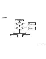
Here is trouble shooting flow related audio.

Audio problem

Only

Speaker out?

YES

NO

UI setting

correct?

Volume, SP off/On

HP Link

Analog

Channel

Problem?

Digital

Channel

Problem?

HDMI

Problem?

Set correctly or
reset by menu.

Check
Speaker or BGC board

NO

YES

NO

NO

Check
BGC board

Check
BGC board

Check
BGC board

YES

YES

YES

NO

Check
BGC board

5. Audio Problem (Flow Chart_D)

Содержание BRAVIA KDL-40Z4500

Страница 1: ...671B63DA146255667FE11BD8887335EC9 SERVICE MANUAL EG1L CHASSIS LCD Digital ColourTV MODEL KDL 40Z4500 KDL 46Z4500 KDL 52Z4500 COMMANDER RM SD001 RM SD001 RM SD001 DEST Chinese Chinese Chinese MODEL COMMANDER DEST RM SD001 KDL 40Z4500 46Z4500 52Z4500 ...

Страница 2: ... 720p 50 60 Hz 576p 576i 480p 480i Y 1 Vp p 75 ohms 0 3V sync negative PB CB 0 7 Vp p 75 ohms PR CR 0 7 Vp p 75 ohms AUDIO Audio input 500 mVrms 47 kilohms HDMI IN 1 2 3 Video 1080 24p 1080p 50 60 Hz 1080i 50 60 Hz 720p 50 60 Hz VIDEO Video output AUDIO OUT Audio output PC IN RGB PC Input D sub 15 pin G 0 7 Vp p 75 ohms non Sync on Green B 0 7 Vp p 75 ohms R 0 7 Vp p 75 ohms HD 1 5 Vp p VD 1 5 Vp ...

Страница 3: ... 1280 768 60 3 75 1360 768 47 7 60 VESA SXGA 1280 1024 64 0 60 VESA Refer to SJ T11348 2006 Methods of measurement for digital television flat panel displays These values are required by SJ T11343 2006 General specification for digital television LCD displays in normal temperature PC input signal reference chart for HDMI IN 1 2 3 Resolution Horizontal frequency kHz Vertical frequency Hz Standard S...

Страница 4: ... not modify the original design without obtaining written permission from the manufacturer or you will void the original parts and labor guarantee USE CAUTION WHEN HANDLING THE LCD PANEL When repairing the LCD panel be sure you are grounded by using a wrist band When repairing the LCD panel on the wall the LCD panel must be secured using the 4 mounting holes on the rear cover 1 Do not press on the...

Страница 5: ...must not exceed 0 5 mA 500 microamperes Leakage current can be measured by any one of three methods 1 A commercial leakage tester such as the Simpson 229 or RCA WT 540A Follow the manufacturers instructions to use these instructions 2 A battery operated AC milliampmeter The Data Precision 245 digital multimeter is suitable for this job 3 Measuring the voltage drop across a resistor by means of a V...

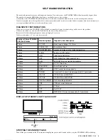
Страница 6: ...iagnostic items are displayed on screen If the screen displays a 0 no error has occurred Number of times STANDBY LED Red flashes Monitoring Items Diagnostic Item Description 2 times DC_DET Main Supply Voltage 12V Error 6 times PANEL_DET Panel detect Error 7 times TEMPERATURE monitor an Increase of an Inside temperature 8 times AUDIO Audio error SP protect 9 times HFR High Frame Rate Error 10 times...

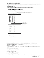
Страница 7: ...ostic screen After you have completed the repairs clear the result display to 0 Clearing the result display To clear the result display to 0 press button on the remote commander sequentially as shown below when the diagnostic screen is being displayed Delection of Error Count and Error History Press 8 button Press button Delection of Panel Operation Time Press 7 button Press button Quitting Self d...

Страница 8: ...HFR Error RED 9 times blink 16 4 7 DEF Error RED 10 times blink 16 4 8 NVM Error RED 11 times blink 16 4 9 I2C Error RED 12 times blink 16 4 10 Balancer Error RED 13 times blink 17 4 11 HDMI Error RED 14 times blink 17 4 12 Tuner Error RED 15 times blink 17 4 13 I2C CH1 Error RED 16 times blink 18 4 14 I2C CH0 Error RED 17 times blink 18 4 15 Digital modulator Error RED 18 times blink 18 4 16 USB ...

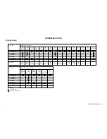
Страница 9: ...inks Blinks Blinks BGC COMPL D5 COMPL 52 D4 COMPL 52 G6 COMPL Panel Module Flowchart Reference C C C C C C C C C C C C C C C B Problem Power_ Back I2C I2C I2C D DET Light TEMP Audio DFE NVM VCT Balancer HDMI Tuner CH1 CH0 Demod USB VCTP Reference Video distorted or missing No Video No No Video No BL OK Video BL OK Tuner No No OSD OK No BL No OSD Video OK HDMI Audio BGC COMPL D5 COMPL 52 D4 COMPL 5...

Страница 10: ...AA671B63DA146255667FE11BD8887335EC9 KDL 40 46 52Z4500 CH 10 2 FLOW CHART Troubleshooting YES Set Power NO See 3 No Power Chart_B See 5 Audio Problem Chart_D See 6 Video problem Chart_E Audio Video Red blinks LED Green See 4 Self Diagnosis Chart_C ...

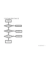
Страница 11: ...7FE11BD8887335EC9 KDL 40 46 52Z4500 CH 11 No 207 253VAC Inlet on Power Board Yes 3 3VDC CN6401 3Pin on BGC board NO Power Board No STBY3 3V YES NO YES AC cable or AC inlet No Power No relay clicks Does Power button work BGC board 3 No Power Flow Chart_B Switch Unit ...

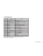
Страница 12: ...nosis mode Red LED Blink When self diagnosis happens STBY Red LED blinks and the history can be seen on display by self diagnosis mode 4 Self Diagnosis EEPROM Error not read write available NVM Error 11 times No Acknowledge detected Digital Demod 18 times I2C Ch1 Error in MOUTON I2C CH1 MOUTON TAS 16 times HDCP cannot be setup correctly HDMI Error 14 times If circuit or PLL circuit do not respond ...

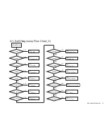
Страница 13: ...4 times YES See 4 11 HDMI Error NO 8 times YES See 4 5 Audio Error 4 1 Self Diagnosis Flow Chart_C NO 15 times YES See 4 12 Tuner Error NO 16 times YES See 4 13 I2C CH1 Error NO 10 times YES See 4 7 DEF Error NO 11 times YES See 4 8 NVM Error NO 12 times YES See 4 9 I2C Error NO 17 times YES See 4 14 I2C CH0 Error 18 times YES See 4 15 Digital modulator Error NO 19 times YES NO 21 times YES See 4 ...

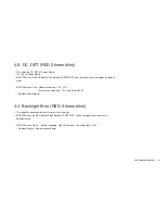
Страница 14: ...s down chassis power to standby status MOUTON micro Pin6 Normal condition 1 3V 2 5V Error case lower than 1 3V or higher than 2 5V Replace Power Board 4 3 Backlight Error RED 6 times blink This indicates panel power circuit error such as inverter MOUTON micro on BGC board Pin40 detects PANEL_DET and shuts down chassis power to standby status MOUTON micro Pin40 Normal condition High Error case Low ...

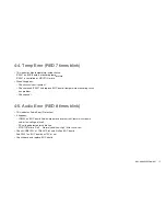
Страница 15: ...ironment Check around IC5507 and replace BGC board if temperature monitoring circuit has problem Check panel 4 5 Audio Error RED 8 times blink This indicates Audio Error Protection It happens IC8200 on BGC board Audio Amp detects over current thermal shut down and or low voltage of itself DC voltage detected for audio line MOUTON micro Pin5 Normal condition High Error case Low Check UNREG15V at CN...

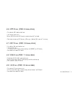
Страница 16: ...TON NVM communication error MOUTON micro on BGC board is communicating with NVM on BGC board Check above and replace BGC board 4 9 I2C Error RED 12 times blink This indicates I2C communication error VCTP micro on BGC board is communicating with each devices on BGC board Check above and replace BGC board 4 6 HFR Error RED 9 times blink This indicates HFR Communication error HFR Communication error ...

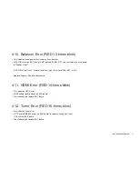
Страница 17: ...ts down chassis power to Standby status MOUTON micro Pin40 Normal condition High Error case Mid 0 85 2 65V Replace Panel or Power Inverter board 4 11 HDMI Error RED 14 times blink This indicates HDCP error HDMI setting trouble matter on BGC board Check above and replace BGC board 4 12 Tuner Error RED 15 times blink This indicates Tuner error VCTP and EMMA3SL micro on BGC board is communicating wit...

Страница 18: ...cessor IC3201 on BGC board Check above and replace BGC board 4 14 I2C CH0 Error RED 17 times blink This indicates I2C communication error MOUTON micro on BGC board is communicating with Real time clock IC5502 on BGC board Check above and replace BGC board 4 15 Digital modulator Error RED 18 times blink This indicates Tuner error EMMA3SL micro is communicating with inside of the Tuner TU2200 on BGC...

Страница 19: ...0 CH 19 4 16 USB Error RED 19 times blink This indicates USB error EMMA3SL micro found out USB over current detection on BGC board Check above and replace BGC board 4 17 VCTP Error RED 21 times blink This indicates VCTP error VCTP micro IC4701 does not work normaly Check above and replace BGC board ...

Страница 20: ... related audio Audio problem Only Speaker out YES NO UI setting correct Volume SP off On HP Link Analog Channel Problem Digital Channel Problem HDMI Problem Set correctly or reset by menu Check Speaker or BGC board NO YES NO NO Check BGC board Check BGC board Check BGC board YES YES YES NO Check BGC board 5 Audio Problem Flow Chart_D ...

Страница 21: ...m All inputs have problem YES NO Analog Channel Problem Digital Channel Problem HDMI Problem Check LVDS harness Power Board BGC board Panel Module NO NO Check BGC board Check BGC board Check BGC board YES YES YES NO Check BGC board NO Check BGC board YES YES Back Light turn on OSD appear NO Check LVDS harness BGC board Panel Module 6 Video Ploblem Flow Chart_E ...

Страница 22: ...S USB V Out A Out HP Out HDMI A IN PC A IN MAIN AMP DDR DDR HDMI1 HDMI2 HDMI3 DMP Opt Out TEMP Sens NVM I2C_EXTRA I2C_TAS I2C_RTC RTC I2C NVM PC IN EMMA3SL MPEG AVC Dec VCT Premium A V SW C Dec 3D Comb ADC NR Histogram HDMI Dec Scaler V SW DDR DDR NAND FLASH Video IN Side BASI Audio Comp1 Video IN1 Sin Video IN2 Comp2 Digital TU CH HK BGC Caye nne S x2 H4 Logo LED Ether Hotel D4Z 40 46 D4 D5 52 DI...

Страница 23: ...R ILLUMINATION Module LCD PANEL BOARD LAYOUT BACK VIEW H4 Board H3VM Board H1VM Board AWF Board TOUCH SENSOR Module Part No Description A 1494 142 A AWF MOUNT A 1552 097 B G6 COMPL A 1557 278 A D4Z COMPL A 1557 911 A H4 COMPL A 1557 912 A H1VM COMPL A 1617 902 A H3VM COMPL A 1641 083 A BGC COMPL 1 480 680 11 ILLUMINATION MODULE 1 798 150 12 TOUCH SENSOR MODULE 1 802 823 11 LCD PANEL 40INCH FHD 3TF...

Страница 24: ...281 A D4Z COMPL A 1557 911 A H4 COMPL A 1557 912 A H1VM COMPL A 1617 902 A H3VM COMPL A 1641 084 A BGC COMPL 1 480 680 11 ILLUMINATION MODULE 1 798 150 12 TOUCH SENSOR MODULE 1 802 822 11 LCD PANEL 46INCH FHD 3TFT SPEAKER INVERTER Board T CON G6 Board D4Z Board BGC Board SPEAKER ILLUMINATION Module LCD PANEL H4 Board H3VM Board H1VM Board AWF Board TOUCH SENSOR Module BOARD LAYOUT BACK VIEW ...

Страница 25: ...197 A D5 COMPL A 1557 911 A H4 COMPL A 1557 912 A H1VM COMPL A 1617 902 A H3VM COMPL A 1641 085 A BGC COMPL 1 480 680 11 ILLUMINATION MODULE 1 798 150 12 TOUCH SENSOR MODULE 1 802 821 11 LCD PANEL 52INCH FHD 3TFT SPEAKER INVERTER Board T CON G6 Board D4 Board BGC Board SPEAKER ILLUMINATION Module LCD PANEL H4 Board H3VM Board H1VM Board AWF Board TOUCH SENSOR Module BOARD LAYOUT BACK VIEW INVERTER...

Страница 26: ... 46 52Z4500 CH 26 PACKING MATERIALS 1 KDL 40Z4500 REF No PART No DESCRIPTION MARK REF No PART No DESCRIPTION MARK 1 4 127 258 01 CUSHION LOWER 2 4 127 257 01 CUSHION UPPER 3 4 127 231 02 INDIVIDUAL CARTON 4 1 480 911 12 REMOTE COMMANDER RM SD001 5 1 835 188 11 POWER SUPPLY CORD 5 4 3 2 1 ...

Страница 27: ...KDL 46Z4500 51 52 53 54 55 56 57 REF No PART No DESCRIPTION MARK REF No PART No DESCRIPTION MARK 51 4 127 256 01 TRAY 52 4 127 255 01 CUSHION LOWER 53 1 835 188 11 POWER SUPPLY CORD 54 1 480 911 12 REMOTE COMMANDER RM SD001 55 4 127 254 01 CUSHION UPPER 56 4 127 230 01 INDIVIDUAL CARTON 57 4 081 035 01 JOINT ...

Страница 28: ...4500 REF No PART No DESCRIPTION MARK REF No PART No DESCRIPTION MARK 101 4 128 214 01 TRAY 102 4 128 216 01 CUSHION LOWER 103 1 480 911 12 REMOTE COMMANDER RM SD001 104 1 835 188 11 POWER SUPPLY CORD 105 4 128 215 01 CUSHION UPPER 106 4 128 213 01 INDIVIDUAL CARTON 107 4 081 035 01 JOINT 101 102 103 104 105 106 107 ...

Страница 29: ...D846660B279CC0D5520DEF8E80C6FD0B0509C3DE5F2E1AA671B63DA146255667FE11BD8887335EC9 KDL 40 46 52Z4500 CH 29E Sony EMCS Corporation Inazawa TEC English 2008KL08 Data Made in Japan 2008 11 9 888 237 01 ...

Отзывы: