Sony Bravia KDL-32EX705 Скачать руководство пользователя страница 15

KDL-32EX705/40EX705/46EX705/52EX705/60EX705  

10

Components not identi ed by a part number or 
description are not stocked because they are seldom 
required for routine service.

The component parts of an assembly are indicated by the 
reference numbers in the far right column of the parts list 
and within the dotted lines of the diagram.

Items marked with an asterisk are not stocked since 

they are seldom required for routine service.  Expect 
some delay when ordering  these components.

NOTE: The components identi ed by shading 
and 

!

 mark are critical for safety. Replace only 

with part number speci ed. 

NOTE: The components identi ed by a red outline and a   mark contain 
con dential information. Speci c instructions must be adhered to whenever 
these components are repaired and/or replaced. 
See Appendix A: Encryption Key Components in the back of this manual. 

SEC 1. DISASSEMBLY/PART NUMBER INFORMATION

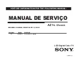
1-1.  TABLE-TOP STAND ASSEMBLY REMOVAL

A   Remove 4 screws from Table-Top Stand Assembly

B   Lift up TV set to detach from Table-Top Stand Assembly


REF. NO.  

PART NO. 

DESCRIPTION 

[ASSEMBLY INCLUDES]


REF. NO.  

PART NO. 

DESCRIPTION 

[ASSEMBLY INCLUDES]


A-1771-200-A 

STAND (LLL3A) ASSEMBLY 

[3-6]


(KDL-60EX705 

ONLY)

 1 

A-1768-636-A  STAND 

(ML3A) 

ASSEMBLY 

[3-6]


(KDL-46EX705 

ONLY)

 1 

A-1768-637-A  STAND 

(LL3A) 

ASSEMBLY 

[3-6]


(KDL-52EX705 

ONLY)


A-1768-634-A 

BASE (M3A) ASSEMBLY


(KDL-32EX705 

ONLY)


A-1768-635-A 

BASE (ML3A) ASSEMBLY


(KDL-40EX705 

ONLY)


4-170-477-01 

COVER, NECK (M3A FRONT)


(KDL-32EX705/40EX705/46EX705 

ONLY)


4-170-479-01 

COVER, NECK (LL3A FRONT)


(KDL-52EX705 

ONLY)


4-170-476-01 

COVER, NECK (LLL3A FRONT)


(KDL-60EX705 

ONLY)


4-170-485-01 

COVER, NECK (M3A REAR)


(KDL-32EX705/40EX705/46EX705 

ONLY)


4-170-487-01 

COVER, NECK (LL3A REAR)


(KDL-52EX705 

ONLY)


4-170-488-01 

COVER, NECK (LLL3A REAR)


(KDL-60EX705 

ONLY)


4-170-449-01 

NECK (M3A)


(KDL-32EX705 

ONLY)


4-170-450-01 

NECK (ML3A)


(KDL-40EX705/46EX705 

ONLY)


4-170-451-01 

NECK (LL3A)


(KDL-52EX705 

ONLY)


4-170-452-01 

NECK (LLL3A)


(KDL-60EX705 

ONLY)


2-580-608-01 

SCREW, +PSW M5X16


(SCREWS TO ATTACH NECK TO BASE)


2-580-608-01 

SCREW, +PSW M5X16


(SCREWS TO ATTACH TABLE-TOP STAND TO LCD TV)


For product protection and safety reasons, Sony strongly recommends


that you use the screws provided with the TV


CAUTION: These screws cannot be used to secure the TV to


the Wall Mount Brackets


2-580-608-01 

SCREW, +PSW M5X16

B

A

Soft Cloth

C

C   Gently place the TV set face down onto a soft cloth

2

1

5

6

3

4

7

Содержание Bravia KDL-32EX705

Страница 1: ...ANUAL DE SERVIÇO LCD Digital Color TV AZ1 L Chassis 9 888 311 01 Version Date Subject 1 0 3 29 2010 No revisions or updates ORIGINAL MANUAL ISSUE DATE 3 2010 HISTORY INFORMATION FOR THE FOLLOWING MANUAL ...

Страница 2: ...MANUAL DE SERVIÇO LCD Digital Color TV AZ1 L Chassis 9 888 311 01 SelfDiagnosis Supported model ...

Страница 3: ...ELOS MODEL COMMANDER DESTINATION MODEL COMMANDER DESTINATION 9 888 311 01 KDL 32EX705 RM YD047 BRAZIL KDL 40EX705 RM YD047 BRAZIL KDL 46EX705 RM YD047 BRAZIL KDL 52EX705 RM YD047 BRAZIL KDL 60EX705 RM YD047 BRAZIL ...

Страница 4: ...3 Speakers Speaker Brackets and HLR Board Removal 12 1 4 GE3A GE2A GE2B Power Boards BAL Board HMS2 Board Lens and LCD Panel Removal 13 1 5 Cleaning the LCD Panel 14 1 6 Screw Legend 14 1 7 Connectors 15 1 7 1 KDL 32EX705 40EX705 15 1 7 2 KDL 46EX705 52EX705 15 1 7 3 KDL 60EX705 16 1 8 Accessories and Packaging 16 1 9 Miscellaneous 16 1 10 Remote Commander 16 SEC 2 Service Adjustments 17 2 1 Acces...

Страница 5: ... 2 2 2 Selecting the Model 19 2 2 3 Selecting the Destination 20 2 2 4 Verifying the Model and Panel Information 21 2 2 5 Reconnecting All Cables 22 2 3 White Balance Adjustments 22 2 4 Resetting the TV to Factory Condition 23 2 4 1 Resetting the TV to Factory Condition Using Service Mode 23 SEC 3 Diagrams 24 3 1 Circuit Boards Location 24 3 2 Block Diagram 25 ...

Страница 6: ... y a l p s i D ontal 1 080 lines vertical Speaker mm Full range with speaker box 2 34 160 Dimensions withstand mm 1 431 909 386 1 252 805 350 1 118 730 280 985 655 280 811 539 250 withoutstand mm 1 431 877 66 1 252 775 65 1 118 698 65 985 623 64 811 507 65 wall mount hole pattern mm 0 0 2 0 0 2 0 0 3 0 0 3 0 0 3 0 0 4 wall mount screw size mm M6 length refer to diagram on page 14 Mass with stand k...

Страница 7: ...f this receiver is directly connected to the AC power line SAFETY RELATED COMPONENT WARNING Components identiſed by shading and mark on the exploded views are critical for safe operation Replace all components with Sony parts whose part numbers appear as shown in this manual or in supplements published by Sony It is essential that all critical parts be replaced only with the part number speciſed i...

Страница 8: ... in areas of high humidity for an extended period of time 4 Do not expose the LCD panel to direct sunlight 5 Avoid contact with water It may cause a short circuit within the module 6 Disconnect the AC power when replacing the inverter circuit High voltage occurs at the inverter circuit at 650Vrms 7 Always clean the LCD panel with a soft cloth material 8 Use care when handling the wires or connecto...

Страница 9: ... certain that you have replaced all the insulators 4 Look for unauthorized replacement parts particularly transistors that were installed during a previous repair Point them out to the customer and recommend their replacement 5 Look for parts which though functioning show obvious signs of deterioration Point them out to the customer and recommend their replacement 6 Check the line cords for cracks...

Страница 10: ...cale The Simpson s 250 and Sanwa SH 63TRD are examples of passive VOMs that are suitable Nearly all battery operated digital multimeters that have a 2 VAC range are suitable see Figure A HOW TO FIND A GOOD EARTH GROUND A cold water pipe is a guaranteed earth ground the cover plate retaining screw on most AC outlet boxes is also at earth ground If the retaining screw is to be used as your earth gro...

Страница 11: ...ror the LED will identify the ſrst of the problem areas Result for all of the following diagnostic items are displayed on screen If the screen displays a 0 no error has occurred Diagnostic Item Diagnostic Item Description Number of times Standby LED blinks Possible Location RGB_SEN RGB Sensor ACK Error NA NA MAIN_POWER Main Power Over Voltage Protection 2 GE3A Power Board KDL 32EX705 40EX705 Only ...

Страница 12: ...05 46EX705 52EX705 60EX705 7 SELF DIAGNOSIS FUNCTIONS STANDBY LED FLASH COUNT Ambient Sensor IR Infrared Receiver Picture Off Timer LED Standby LED Power LED 2 times 5 times LED ON 0 3 sec LED OFF 0 3 sec LED OFF 3 sec ...

Страница 13: ...lure time beforehand Error history Failure time before last Error history The last failure time Item name STBY LED flash time Total operation time by hour MAX 65535 Boot count MAX 65535 Panel operation time by hour MAX 65535 Error count 00 99 Error history Last failure time beforehand Error history Failure time before last Error history The last failure time Item name STBY LED flash time Total ope...

Страница 14: ...ve completed the repairs to be sure you have cleared the result display to 0 1 To clear the Error history and Error count Press the Channel 8 Channel 0 2 To clear the Panel operation time Press the Channel 7 Channel 0 EXITING THE SELF CHECK DIAGNOSTIC SCREEN 1 To exit the Self Diagnostic screen turn off the power to the TV by pressing the POWER button on the remote or the POWER button on the TV SE...

Страница 15: ...O PART NO DESCRIPTION ASSEMBLY INCLUDES 1 A 1771 200 A STAND LLL3A ASSEMBLY 3 6 KDL 60EX705 ONLY 1 A 1768 636 A STAND ML3A ASSEMBLY 3 6 KDL 46EX705 ONLY 1 A 1768 637 A STAND LL3A ASSEMBLY 3 6 KDL 52EX705 ONLY 2 A 1768 634 A BASE M3A ASSEMBLY KDL 32EX705 ONLY 2 A 1768 635 A BASE ML3A ASSEMBLY KDL 40EX705 ONLY 3 4 170 477 01 COVER NECK M3A FRONT KDL 32EX705 40EX705 46EX705 ONLY 3 4 170 479 01 COVER ...

Страница 16: ...WER SWITCH 59 4 176 944 01 BRACKET VESAT ML 2 580 639 01 SCREW BVTP 4X12 TYPE2 IT 3 2 580 611 01 SCREW PSW M6X16 2 580 600 01 SCREW PSW M4X8 KDL 32EX705 ONLY 2 580 592 01 SCREW PSW M3X8 4 159 298 01 SCREW PSW M4X10 2 580 591 01 SCREW PSW M3X5 7 685 646 79 SCREW BVTP 3X8 TYPE2 IT 3 2 580 603 01 SCREW PSW M4X16 ALL EXCEPT KDL 32EX705 51 52 53 54 55 56 57 58 59 A F H J K L 32 40 46 52 60 I G C B E D ...

Страница 17: ...EL A ALL EXCEPT KDL 32EX705 102 4 169 425 01 BRACKET SP 32R KDL 32EX705 ONLY 102 4 169 427 01 BRACKET SP 40R KDL 40EX705 ONLY 102 4 171 123 01 BRACKET SP 46R KDL 46EX705 ONLY 102 4 169 431 01 BRACKET SP 52R KDL 52EX705 ONLY 102 4 169 433 01 BRACKET SP 60R ASSY KDL 60EX705 ONLY 103 1 826 873 41 LOUDSPEAKER 3 4X17 5CM 104 4 169 424 01 BRACKET SP 32L KDL 32EX705 ONLY 104 4 169 426 01 BRACKET SP 40L K...

Страница 18: ...ch from Bezel H Carefully Lift up Panel to remove from Bezel 1 4 GE3A GE2A GE2B POWER BOARDS BAL BOARD HMS2 BOARD LENS AND LCD PANEL REMOVAL 151 X 2547 289 1 BEZEL 32 ASSEMBLY KDL 32EX705 ONLY 151 X 2547 290 3 BEZEL 40 ASSEMBLY KDL 40EX705 ONLY 151 X 2547 291 1 BEZEL 46 ASSEMBLY KDL 46EX705 ONLY 151 X 2547 292 1 BEZEL 52 ASSEMBLY KDL 52EX705 ONLY 151 X 2547 544 1 BEZEL 60 ASSEMBLY KDL 60EX705 ONLY...

Страница 19: ...EW PSW M3X8 BAL 4 GE3A 4 8 Ũ 4 159 298 01 SCREW PSW M4X10 BTM FRM to PNL 1 UC to BTM FRM 5 VESA BRKT to PNL 2 8 ŭ 2 580 591 01 SCREW PSW M3X5 RC to PNL 3 3 Ŭ 7 685 646 79 SCREW BVTP 3X8 TYPE2 IT 3 RC to TRMNL AREA 1 1 Ţ 2 580 603 01 SCREW PSW M4X16 RC to PNL to PNL BRKT 2 2 P N DESCRIPTION REMARKS TOTAL Š 2 580 639 01 SCREW BVTP 4X12 TYPE2 IT 3 RC 10 BTM FRM to BEZ 2 SPKR to SPKR BRKT L 2 SPKR to ...

Страница 20: ...R HMS2 TCON CN6151 CN6102 GE2B SWITCH UNIT POWER SWITCH 252 251 253 254 201 1 910 100 17 HARNESS ASSEMBLY 2 KDL 32EX705 ONLY 201 1 910 100 19 HARNESS ASSEMBLY 2 KDL 40EX705 ONLY 202 1 837 790 11 LVDS LEAD WIRE WITH CONNECTOR KDL 32EX705 ONLY 202 1 837 704 11 LVDS FLEXIBLE FLAT CABLE 51P KDL 40EX705 ONLY 203 1 910 101 36 HARNESS ASSEMBLY 1 KDL 32EX705 ONLY 203 1 910 101 37 HARNESS ASSEMBLY 1 KDL 40...

Страница 21: ...ESCRIPTION ASSEMBLY INCLUDES REF NO PART NO DESCRIPTION ASSEMBLY INCLUDES 303 1 910 101 40 HARNESS ASSEMBLY 1 304 1 837 532 12 CONNECTOR ASSEMBLY 1 8 ACCESSORIES AND PACKAGING 4 180 192 11 MANUAL INSTRUCTION 1 837 635 12 POWER SUPPLY CORD KDL 60EX705 ONLY 1 837 645 12 POWER SUPPLY CORD SET ALL EXCEPT KDL 60EX705 4 180 045 11 SUPPLEMENT STAND INSTALLATION ALL EXCEPT KDL 60EX705 1 9 MISCELLANEOUS A ...

Страница 22: ... second of each other DISPLAY Channel 5 Volume POWER POWER Onscreen cursor and select button DISPLAY 5 VOLUME RM YD047 DIGITAL SERVICE 001 OP 000 VERS MAIN SUB DM1 301J00AA SM1 010W00AA M2 105C SB1 000W00AA DD1 016J00AA SD1 010W00AA DM1 301J00AA RF01 05 WP00 521J00AA ID1C117081 ID1C117081 LTY320AB01 PID04020000 WF 2 0 0 99 BEM WF 0B BM1 012W00LU Camera FW BB1 000W00LU Camera FW BD1 011J46LUX Sampl...

Страница 23: ...Within each Service Menu are Categories and data information CHASSIS SERVICE 000 CXD2813R 000 H_DET_NOSIG_CNT 1 Item number Category number Item name Category name Data Sample Chassis Service Menu 2 1 2 USING THE REMOTE COMMANDER TO VIEW OR CHANGE SERVICE DATA Use the buttons on the Remote Commander to access the Service Menu items and adjust the Data Values DISPLAY Channel Volume POWER 4 To chang...

Страница 24: ...leting the software update proceed to Selecting the Model 2 2 2 SELECTING THE MODEL After replacing the BAL Board or LCD Panel go into Service Mode to set the Model data value 1 TV must be in standby mode Power off 2 Access Service Mode Press the following buttons on the Remote Commander within a second of each other DISPLAY Channel 5 Volume POWER 3 Display the DIGITAL Service Menu NOTE There are ...

Страница 25: ... MODEL 000 SEG 10 3a 0 Data Value Code Name 6 Proceed to Selecting the Destination 2 2 3 SELECTING THE DESTINATION After replacing the BAL Board or the LCD Panel the destination location must be set CAUTION Selecting the incorrect destination may requiring replacing the BAL Board DIGITAL SERVICE 002 MODEL 000 SEG 10 3a 0 7 Press 1 to move to 001 DEST sub Category DIGITAL SERVICE 002 MODEL 001 DEST...

Страница 26: ...ASSIS and SUB If the DIGITAL Service Menu is not displayed press JUMP or OPTIONS on the Remote Commander DIGITAL SERVICE 001 OP 000 VERS MAIN SUB DM1 301J00AA SM1 010W00AA M2 105C SB1 000W00AA DD1 016J00AA SD1 010W00AA DM1 301J00AA RF01 05 WP00 521J00AA ID1C117081 ID PID WF 2 0 0 99 BEM WF 0B BM1 012W00LU Camera FW BB1 000W00LU Camera FW BD1 011J46LUX Model ID Product ID Panel Code 2577368E 345200...

Страница 27: ... press JUMP or OPTIONS on the Remote Commander 3 Press 2 to until the 006 WB Category displays DIGITAL SERVICE 006 WB 000 WHITE_BALANCE ___ 4 Press 0 to enter White Balance Adjustment mode 5 To select the White Balance Adjustment setting that needs to be changed do the following a To select R_DRV press 1 b To select G_DRV press 2 c To select B_DRV press 3 d To select R_BKG press 4 e To select G_BK...

Страница 28: ...E MODE 1 TV must be in Standby Mode POWER off 2 Press the following buttons on the Remote Commander within a second of each other DISPLAY Channel 5 Volume POWER 3 If necessary press JUMP or OPTIONS to go to DIGITAL mode 4 Press 8 SERVICE changes to green RST 5 Press MUTING RST executes the command and displays EXE 6 Press 0 EXE RST displays green then red indicating the TV is writing the data 7 Wh...

Страница 29: ...KDL 32EX705 40EX705 46EX705 52EX705 60EX705 24 SEC 3 DIAGRAMS 3 1 CIRCUIT BOARDS LOCATION GE3A KDL 32EX705 40EX705 Only GE2B KDL 46EX705 52EX705 Only GE2A KDL 60EX705 Only HMS2 SWITCH UNIT HLR BAL ...

Страница 30: ...KDL 32EX705 40EX705 46EX705 52EX705 60EX705 25 DIAGRAMS 3 2 BLOCK DIAGRAM ...

Страница 31: ...ation Sony Technology Center Technical Services Service Promotion Department 9 888 311 01 English 2010CJ74WEB 1 Printed in USA 2010 3 is a trademark of Sony Electronics Reproduction in whole or part without written permission is prohibited All rights reserved ...

Отзывы: