


– 21 –
KDF-E42/50A12U
RM-ED002
44
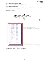
Troubleshooting
C
h
e
c
k
wh
et
he
r
th
e
1
(
s
ta
ndby)
indic
ator
is f
las
hing in
red.
When it is
flashing
The
self-diagnosis function is activated.
1
Me
asure
ho
w l
ong
the
1
(stan
dby) indi
cato
r
flash
es
a
nd stops fl
ashin
g.
F
o
r
exa
m
ple,
the in
dic
ator flashe
s for
two se
conds,
stops
flashing for
on
e
secon
d, and fla
sh
es
for two seconds.
2
Pr
ess
1
on the TV (Front side)
to switch it
off, disc
o
nnect
the mains lead,
and
inform your deal
er or
Sony
service
centre
of h
o
w
th
e i
ndi
ca
to
r flash
es (d
uration
an
d
interval).
When it is
no
t
flashing
1
Check
th
e
items in
the
tabl
es
belo
w.
2
If th
e
p
roble
m
still pe
rsi
sts,
h
a
ve your TV serviced
b
y
qu
alifie
d se
rvice person
nel.
Picture
Pr
oble
m
Caus
e/Reme
dy
No
pi
ctu
re
(screen
is
dark) a
nd
no soun
d
•
Check the
aerial connection.
•
Connect
the
TV to the
mains, and pr
ess
1
on the TV (front
sid
e).
•
If the
1
(stand
by)
indicator
lights up in red
, press
TV
"
/
1
.
No
pi
ct
ure
or n
o me
nu
inf
ormat
io
n from equ
ipme
nt
conne
cte
d to t
he scart
conne
cto
r
•
Check that
the optional
equipment
is
on an
d
press
/
repeatedly until
the
correct inp
ut symbol is displayed on the
scr
een.
•
Check the
connection
between the
optional equipment and
th
e TV.
Di
st
orte
d p
ict
ure
•
W
hen installing optional equipment, leave som
e space bet
ween the opt
ional
equipment and
th
e TV.
•
W
hen changing progr
ammes or selecting digital/anal
ogue Text, turn off any
equipment
con
nected
to
the
scart connector on
th
e
rear of
th
e
TV.
Do
ubl
e i
m
age
s o
r gh
ost
ing
•
C
hec
k ae
ria
l/c
abl
e conn
ect
ions.
•
C
he
ck the
ae
ria
l loca
tion a
n
d
dire
ction.
O
n
ly sno
w and
no
ise
a
ppear
on th
e
s
c
reen
•
C
heck if the
aerial is broken
or bent.
•
C
he
ck if the
ae
ria
l has
re
ac
he
d the
end
of
its
se
rvic
ea
b
le
life
(three
to five
years in nor
mal u
se,
one to
two
years at
the seaside).
Pi
ctu
re
(dot
te
d li
nes
or stri
pes)
noi
se
•
K
ee
p t
h
e
TV
away
from
e
le
ct
ric
al
noi
se
sourc
es
suc
h
as c
ars, m
o
torc
yc
les,
or hair
-dryers.
•
M
ake sure that th
e
aerial is conne
cted using the
supplied
coaxial
cable.
•
K
eep
the aerial cable
away from other connecting cables.
•
D
o not use a 300
-ohm
twin
lead
cable
as interfer
ence
may occur
.
Pi
ctu
re
n
o
is
e whe
n
v
iewi
ng
a
TV ch
anne
l
•
S
el
ec
t “Ma
nual
Pr
ogram
me
Preset
” i
n
the
“Se
t Up”
me
nu and
adj
ust
“AFT”
(Automatic
Fine Tuning)
to
obtain better
pictur
e reception (p
age
31)
.
•
S
elect “Noise
Reduc
tion” in the “Pic
ture
Adju
stment”
menu to red
uce
the
noise in
th
e
picture (page
22).
St
ripe
no
ise
du
ring
pl
ayb
ack/
re
cordi
ng of
a VCR
•
V
ideo
head interference.
Ke
ep your VCR
away from
the TV
.
•
L
eave
a
space
of 30 cm
between your VCR
and
the TV to avo
id noise.
•
A
void installing your VC
R
in
fro
nt of
the TV or
b
eside
the TV.
Some
t
in
y
b
lac
k p
oin
ts
an
d/o
r
brigh
t poi
nt
s on th
e
s
c
reen
•
T
he pictu
re
of a display
unit is comp
osed of
pixels. Tiny black points and/o
r
brigh
t
p
oints (pixels) on
the screen do not indicate a
malf
unction.
No
co
lou
r
on
prog
ra
mmes
•
S
elect
“Reset
”
in
the “Pict
ure Adjust
ment” menu to ret
urn to the
fact
ory
se
tt
ings (page
22
).
No
co
lou
r or irregu
lar col
our
wh
en vi
ewi
ng a
sig
nal
f
ro
m t
he
Y
, PB
/CB
, PR/
CR jacks of
3
•
Check
the connection of
th
e
Y,
P
B
/C
B
, P
R
/C
R
jacks of
3.
•
M
ake sure
that the
Y,
P
B
/C
B
, P
R
/C
R
j
ac
k
s
of
3 a
re
firm
ly se
at
ed i
n
t
h
ei
r
respective sockets.
Sou
nd
Pr
oble
m
Caus
e/Reme
dy
No
so
und,
but
go
od
pi
ctu
re
•
P
re
ss
2
+/
–
o
r
%
(Mute).
•
C
he
ck that
“TV Spe
ake
rs”
is s
et to “
o
n”
in the
“F
ea
ture
s”
me
nu (page
26).
No
isy sou
n
d
•
S
ee the “Picture
noise” causes/remedies
on page
44.
Channels
Pr
oble
m
Caus
e/Reme
dy
The d
esi
re
d chan
nel
c
anno
t be
sel
ected
•
S
witch between
digital and
analogue mode
an
d select
the desired
digital/
ana
logu
e cha
nnel
.
Some
ch
anne
ls are bl
ank
•
S
crambled/Subscription only channel.
Subscribe to the
Pay
Per View
se
rvi
ce
.
•
Chan
nel is used only for
data (no picture
or sound).
•
Contact
the broadcaster for transmission details.
Di
gi
tal
chan
nel
i
s
not
di
spl
aye
d
•
Check
that the
aerial
is p
lugged directly into
the TV (not through
other
equipment).
•
C
ontact
a
lo
cal installer to find out if
dig
ital transm
issions are
pro
vided
in
your area.
•
U
pgrad
e to a higher
g
ain aerial.
Gen
eral
Pr
oble
m
Caus
e/Reme
dy
T
he TV
t
u
rn
s
of
f
automati
cal
ly
(t
he T
V
ent
ers sta
ndby
mod
e)
T
h
e TV
t
u
rn
s
on
automati
cal
ly
•
Check if the
“Timer
” is
activated (page
28).
•
If no
sign
al is received or no
op
eration
is perf
ormed
in
the TV mode
for
10
minutes,
the TV automatically switches to standby
mode.
•
Check if the
“Timer
” is
activated (page
28)
Some
i
nput
s
ources
can
not
b
e
sel
ected
•
S
el
ec
t
“A
V Preset
” in the
“
S
et Up” me
nu and ca
nce
l “Ski
p” of
th
e inp
ut
so
urce (p
age
30)
.
The remot
e doe
s
n
ot f
unct
ion
•
R
ep
la
ce
t
h
e
bat
te
rie
s.
The l
amp in
dica
to
r
o
n
fr
on
t
of t
he TV
s
e
t i
s
l
it
.
•
Turn
the
T
V
of
f.
Turn
th
e
TV o
n
a
g
ai
n,
if
the
l
am
p
i
ndic
at
or i
s
stil
l
lit
t
h
en
replace
the internal lamp.
For de
tails
refer to page 39
to
4
1
.
Pr
oble
m
Caus
e/Reme
dy
Continued
45
Additional Information
Содержание Bravia KDF-E42A12U
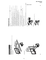
Страница 23: ... 23 KDF E42 50A12U RM ED002 3 7 POWER BLOCK REMOVAL 3 8 OPTICAL UNIT 3 6 N JB AG BOARDS 3 5 SERVICE POSITION 4 ...
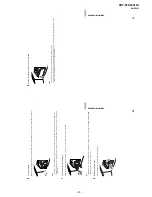
Страница 24: ... 24 KDF E42 50A12U RM ED002 3 10 SCREEN MIRROR BLOCK ASSEMBLY REMOVAL 3 9 C BOARD REMOVAL ...
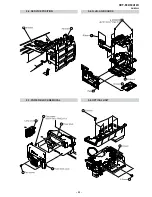
Страница 26: ... 26 KDF E42 50A12U RM ED002 3 13 MIRROR REMOVAL 3 14 H3 REMOVAL 3 15 SPEAKER REMOVAL ...
Страница 41: ...A B C D E F G H I J K L M N 1 2 3 4 5 6 7 8 9 10 11 O 41 AG Printed Wiring Board Conductor Side A ...
Страница 42: ...A B C D E F G H I J K L M N 1 2 3 4 5 6 7 8 9 10 11 O 42 AG Printed Wiring Board Conductor Side B ...
Страница 57: ...A B C D E F G H I J K L M N 1 2 3 4 5 6 7 8 9 10 11 O 57 JB Printed Wiring Board Conductor Side A ...
Страница 58: ...A B C D E F G H I J K L M N 1 2 3 4 5 6 7 8 9 10 11 O 58 JB Printed Wiring Board Conductor Side B ...
Страница 105: ...9 927 517 02 Sony Corporation Sony UK Service Promotions Dept English 06KP7100 1 Printed in U K 2006 11 ...


