
– 31 –
– 32 –
– 34 –
– 33 –
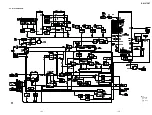
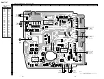
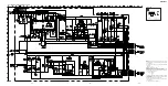
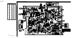
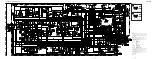
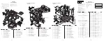
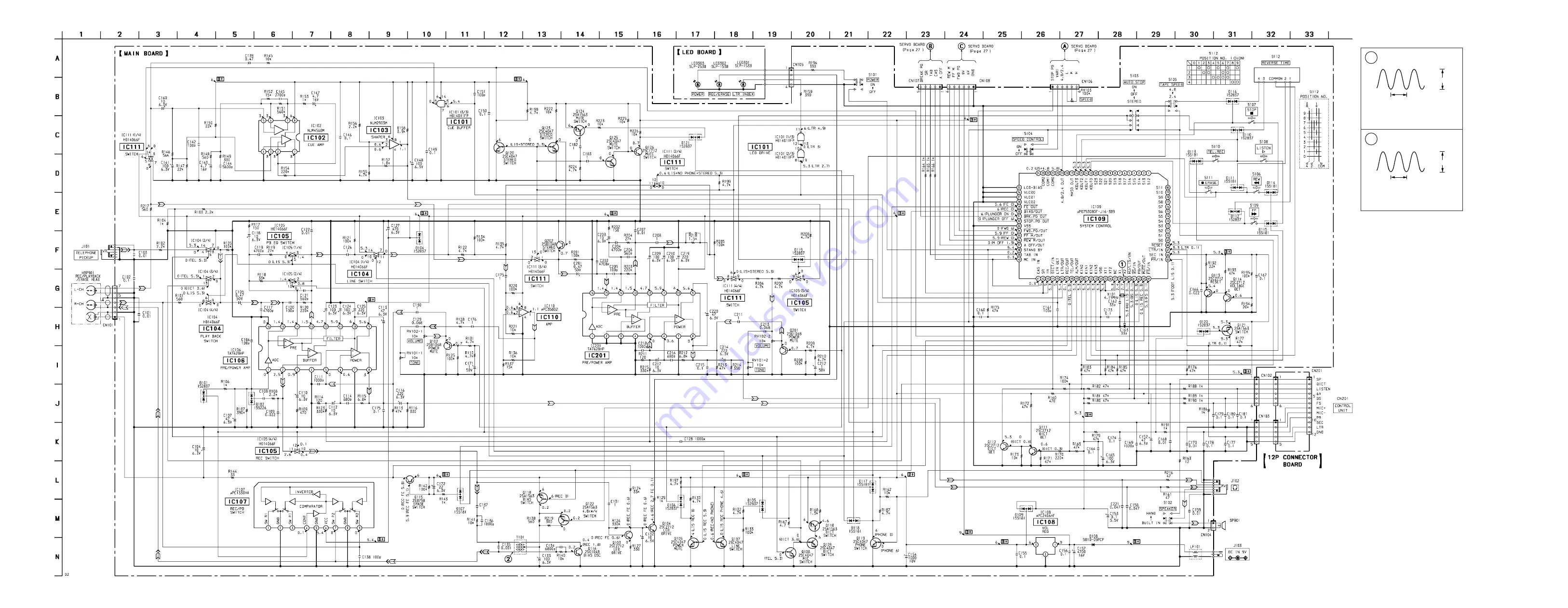
6-6. SCHEMATIC DIAGRAM (MAIN SECTION)
BM-87DST
Note:
• All capacitors are in
µ
F unless otherwise noted. pF:
µµ
F
50 WV or less are not indicated except for electrolytics
and tantalums.
• All resistors are in
Ω
and
1
/
4
W or less unless otherwise
specified.
•
U
: B+ Line.
• Power voltage is dc 9 V and fed with regulated dc power
supply from external power voltage jack (J103).
• Voltages and waveforms are dc with respect to ground
under no-signal conditions.
no mark
: STOP
LIS
: LISTEN
FE
: FAST-ERASE
REC
: DICT/TEL-REC
F
: FF
R
: REW
FWD
: LISTN, DICT, TEL, LTR
M-OFF
: MOTOR OFF
M-ON
: MOTOR ON
NO-CAS
: NO CASSETTE
HU-LIS
: LISTN mode (HU-80)
FOOT-LIS : LISTN mode (FS-75)
• Voltages are taken with a VOM (Input impedance 10 M
Ω
).
Voltage variations may be noted due to normal produc-
tion tolerances.
• Waveforms are taken with a oscilloscope.
Voltage variations may be noted due to normal produc-
tion tolerances.
• Circled numbers refer to waveforms.
• Signal path.
E
: PB
a
: REC
z
Waveforms
1
2
IC109
tl
X2
T101
VOLT/DIV : 0.5 V AC
TIME/DIV : 50 nsec
VOLT/DIV : 2 V AC
(X10ATT : ON)
TIME/DIV : 5
µ
sec
3 Vp-p
4.19 MHz
50 Vp-p
12.5
µ
sec
Содержание BM-87DST Marketing
Страница 3: ... 3 SECTION 2 GENERAL This section is extracted from instruction manual ...
Страница 4: ... 4 ...
Страница 5: ... 5 ...
Страница 6: ... 6 ...
Страница 7: ... 7 ...
Страница 8: ... 8 ...
Страница 9: ... 9 ...
Страница 10: ... 10 ...
Страница 11: ... 11 ...
Страница 12: ... 12 ...
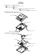
Страница 16: ... 16 3 7 MOTOR FWD ASSY M901 3 1 2 Motor FWD ASSY M901 Mechanism deck Cushion M ...
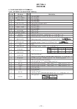
Страница 21: ... 21 22 BM 87DST 6 2 BLOCK DIAGRAM Note Signal path E PB a REC ...
Страница 31: ... 43 BM 87DST MEMO ...


