background image

4-28

DVS-7200AE IM

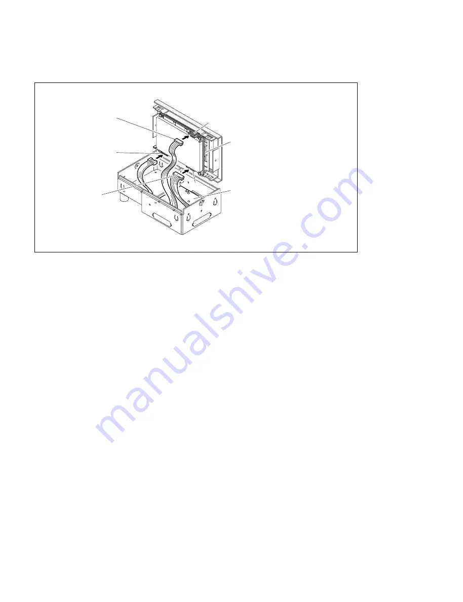
(5) Connect the three harnesses of the IF-629 board to the CN1 through CN3 on the KY-328/329/393/

395C board.

(6) Secure the AD panel to the adaptor box by the two screws.

(7) Turn on the power switches A and B in the control panel.

(If the one power unit is installed, turn on the power switch of the installed power unit.)

(Refer to “4-4-2. Turning On/Off the Power Switch”.)

(8) Close the panel.  (Refer to “4-4-1. Opening and Closing of Panel”.)

CN1

KY-328/329/393/395C board

CN2

IF-629 board

Red

CN3

White

4-4. Installation of Options for Control Panel

Содержание BKDS-7025

Страница 1: ...25 7026 BKDS 2031 BKDS 2032 BKDS 2041 BKDS 2070 BKDS 7001 BKDS 7002 BKDS 7030 BKDS 7031 BKDS 7033 BKDS 7075 BKDS 7090 BKDS 7091 BKDS 7103 BKDS 7110 BKDS 7111 BKDS 7113 BKDS 7133 BKDS 7161 BKDS 7163 BKDS 7250 BKDS 7270 BKDS 7271 BKDS 7280 BKDS 7340 BKDS 7370 BKDS 7420 BKDS 7444 BKDS 7445 BKDS 7690 BZS 7040A BZS 7060A ...

Страница 2: ...DVS 7200A Serial No 10001 and Higher BKDS 2031 Serial No 10001 and Higher BKDS 2032 Serial No 10001 and Higher BKDS 2041 Serial No 10001 and Higher BKDS 2070 Serial No 10001 and Higher BKDS 7001 Serial No 10001 and Higher BKDS 7002 Serial No 10001 and Higher BKDS 7015 Serial No 10001 and Higher BKDS 7025 Serial No 10001 and Higher BKDS 7026 Serial No 10001 and Higher BKDS 7030 Serial No 10001 and ...

Страница 3: ...the product is installed in Rack 1 Prevention against overloading of branch circuit When this product is installed in a rack and is supplied power from an outlet on the rack please make sure that the rack does not overload the supply circuit 2 Providing protective earth When this product is installed in a rack and is supplied power from an outlet on the rack please confirm that the outlet is provi...

Страница 4: ......

Страница 5: ... Cord 1 1 1 3 Connectors 1 2 1 4 Input and Output Signals of Connectors 1 3 1 4 1 DVS 7200A 1 3 1 4 2 BKDS 7015 1 6 1 4 3 BKDS 7025 7026 1 8 1 5 Examples of System Connection 1 11 2 Installation of DVS 7200A 2 1 External Dimensions 2 1 2 2 Rack Mounting 2 2 3 Installation of Control Panel 3 1 External Dimensions 3 1 3 2 Installation Space 3 3 3 3 Installation of MAIN PANEL 3 4 3 4 Installation of ...

Страница 6: ... Switch 4 15 4 4 3 Installation of BKDS 7001 Control Port Expansion Board 4 16 4 4 4 Installation of BKDS 7002 Source Name Display Unit BKDS 7015 4 17 4 4 5 Installation of BKDS 7031 Track Ball 4 19 4 4 6 Installation of Option Panels BKDS 7030 7031 7033 7340 4 21 4 4 7 Joining of BKDS 7075 Control Panel Remote Adaptor 4 29 4 4 8 Installation of BKDS 7091 Redundant Power Supply Unit BKDS 7015 4 33...

Страница 7: ...n Load of Program 6 6 6 2 2 Initializing of Data on RAM 6 7 6 2 3 Initializing of Nonvolatile Memory 6 8 6 3 Set up 6 9 6 3 1 Confirmation of the Software Version 6 10 6 3 2 Setting of the Signal Format 6 10 6 3 3 Setting about the System 6 11 6 3 4 Saving Set up Data to Nonvolatile Memory 6 12 6 4 Installation of Software for Option Board 6 13 ...

Страница 8: ...intenance Manual Part 1 Supplied with DVS 7200A This manual describes the information for the periodic maintenance and the information for the service with predicated on the replacement of the principal blocks and mounted circuit boards Part number 3 201 866 01 Maintenance Manual Part 2 The following manuals describe the detailed service information For obtaining please contact your local Sony s s...

Страница 9: ...scribes the external dimensions and rack mounting Section 3 Installation of Control panel This section describes the external dimensions installation space rack mounting and replacement of key tops Section 4 Installation of Options This section describes the installation of plug in boards combinations of optional boards and installation of options Section 5 Confirmation in Installation This sectio...

Страница 10: ......

Страница 11: ...imum 35 A for the processor and the control panel respectively If the capacity of the AC power is not the adequately large the breaker of the AC power at the supply side will operate or the unit will abnormal operate 1 2 3 Power Cord w The power cords are not supplied with DVS 7200A and the control panel Be sure to use the power cords that are applicable to the places in the world To avoid a fire ...

Страница 12: ...le SWITCHER 2 D sub 9 pin Male DME 2 Connector 9 pin Male TERMINAL 1 to 2 2 1 560 651 00 1 REMOTE 1 to 4 2 Junction Shell 9 pin 1 561 749 00 OPTION PANEL 2 BVS Cable 1 574 993 11 AC IN 2 Main Power Supply Cable For the details of the cable refer to Section 1 2 3 3 BKDS 7025 7026 Connector function name Connector parts No and on rear panel name of cable SWITCHER D sub 9 pin Male DME Connector 9 pin...

Страница 13: ... A Transmited VD signal _ 3 Control Panel BKDS 2010 etc PANEL 2 Keyer Remote Panel BKDS 7060 etc REMOTE 3 1 4 Input and Output Signals of Connectors EXT VIEW 1 13 14 25 D SUB 25 PIN FEMALE Rear panel D SUB 9 PIN FEMALE EXT VIEW 1 5 6 9 GPI TERMINAL REMOTE 4 MATRIX SERIAL TALLY DME 2 DME 4 PANEL 1 DME 1 DME 3 PANEL 2 REMOTE 3 EDITOR B REMOTE 2 EDITOR A REMOTE 1 m 1 CONTROLLER Controlling device 2 D...

Страница 14: ... data 8 RX A Received data _ 9 FG Frame Ground MATRIX 4 D sub 9 pin Female DEVICE 1 to Routing switcher Pin No Signal Name Function 1 FG Frame ground 2 GND Ground 3 DATA Data 4 GND Ground 5 _ _ 6 GND Ground 7 GND Ground 8 GND Ground 9 FG Frame Ground 4 If connecting Sony s Routing Switcher DVS V6464B use the 9 pin BNC conversion cable supplied with DVS 7200A EDITOR A REMOTE 1 RS 422A D sub 9 pin F...

Страница 15: ...2 GND Ground 3 GPI IN 2 4 GPI IN 4 5 GPI IN 6 General purpose input 6 GPI IN 8 7 GPI OUT 1B 8 GPI OUT 2B 9 GPI OUT 3B General purpose relay output B 8 10 GPI OUT 4B 11 GPI OUT 6 12 GPI OUT 8 General purpose open collector output 9 13 GPI OUT COM Ground for open collector output 14 GND Ground 15 GPI IN 1 16 GPI IN 3 17 GPI IN 5 General purpose input 18 GPI IN 7 19 GPI OUT 1A 20 GPI OUT 2A 21 GPI OU...

Страница 16: ...and 8 are short circuitede each other on the CN 1143 board 1 4 2 BKDS 7015 m CONTROLLER 1 Controlling device 1 Main Panel SWITCHER RS 422A D sub 9 pin Female CONTROLLER 1 to Processor DVS 7200A Pin No Signal Name Function 1 FG Frame ground 2 RX A Received data _ 3 TX B Transmitted data 4 GND Common ground 5 FIELD Field signal input 6 GND Common ground 7 RX B Received data 8 TX A Transmitted data _...

Страница 17: ... Ground 8 TCLK Serial clock for character display 9 TWDT Indicate data for character display 10 GND Ground 11 TBLANK Disable signal for character display 12 GND Ground 13 GND Ground 14 12 V Power supply 12 V 15 12 V Power supply 12 V 16 BLANK LED light disable signal 17 GND Ground 18 SEQ Control signal for switch read and LED light 19 RDT Switch read data 20 GND Ground 21 TSEQ Control signal for c...

Страница 18: ...Connectors EXT VIEW 1 13 14 25 1 13 14 25 D SUB 25 PIN FEMALE Rear panel GPI SWITCHER DME TERMINAL1 TERMINAL2 OPTION PANEL REMOTE1 REMOTE2 REMOTE3 REMOTE4 REMOTE5 DISPLAY PANEL D SUB 9 PIN FEMALE EXT VIEW 1 5 6 9 1 5 6 9 1 5 6 9 1 5 6 9 1 5 6 9 1 13 14 25 1 13 14 25 1 5 6 9 1 5 6 9 1 5 6 9 1 5 6 9 1 5 6 9 REMOTE 1 RS 422A D sub 9 pin Female CONTROLLER 1 to External Device Pin No Signal Name Functi...

Страница 19: ...nd 18 SEQ Control signal for switch read and LED light 19 RDT Switch read data 20 GND Ground 21 ELHD EL display horizontal sync signal 22 EL DATA 1 EL display indicate data 1 23 12 V Power supply 12 V 24 12 V Power supply 12 V 25 GND Ground 1 4 Input and Output Signals of Connectors GPI D sub 25 pin Female INPUT x 8 TTL OUTPUT x 4 relay contact 30 V 0 1 A resistance load OUTPUT x 4 open collector ...

Страница 20: ...play 23 12 V Power supply 12 V 24 12 V Power supply 12 V 25 GND Ground n This port is used for special use ready Only when connecting the control harness onto the CN8 of the connec tor on the CN 1143 board this port is enable 2 Display Panel _ D sub 25 pin Female from Main panel Pin No Signal Name Function 1 GND Ground 2 12 V Power supply 12 V 3 SCLK Serial colck for switch read and LED light 4 GN...

Страница 21: ...TERMINAL MATRIX CRK IN x2 x2 INPUTS COMPONENT ANALOG INPUTS COMPONENT ANALOG Y1 U1 V1 S1 Y2 U2 V2 S2 Y3 U3 V3 S3 DME V K INPUTS DIGITAL x4 SUPER V K x4 VTR INPUTS DIGITAL x12 CAMERA INPUTS DIGITAL REF OUT REF IN 1 PANEL REMOTE2 DME SW ER CONTROL OUT1 BKDS 7060 BKDS 2010 KEY BOARD EDITOR DME VTR BVE 9100 MONITOR ME1 ME2 VE WFM DME PANEL SW ER PANEL SW ER K V V K V KZ V KZ DME PANEL SW ER PANEL SW E...

Страница 22: ...DME2 AUX5 AUX6 DME3 AUX8 AUX7 DME4 AUX9 AUX10 AUX11 AUX12 AUX13 EDIT PVW DIRECT IN GPI SERIAL TALLY TERMINAL MATRIX Y4 U4 V4 S4 x2 CRK IN x2 DME V K INPUTS COMPONENT ANALOG INPUTS COMPONENT ANALOG INPUTS DIGITAL INPUTS DIGITAL x4 SUPER V K x4 VTR REF OUT REF IN 1 PANEL ANALOG COMPOSITE INPUTS CAMERA x12 DME PANEL SW ER PANEL KZ K V V V K SW ER KZ V SW ER K V V K SW ER PANEL DME PANEL SW ER K V V K...

Страница 23: ... DVS 7200AE IM Section 2 Installation of DVS 7200A A B 482 424 465 368 3 443 10 UNIT 23 5 40 40 37 35 13 221 5 111 1 28 5 250 8 403 2 8 M4 37 7 5 5 29 29 13 13 477 8 452 Unit mm 88 2 1 External Dimensions ...

Страница 24: ... the rack Make sure that all the units in the rack should be operated within the temperature range of 10 dC to 35 dC 2 Be sure to use the recommended rail when rack mounting The unit cannot be installed completely to a rack by rack angles alone 3 It is recommended to fix the rack to the floor with bolts When the unit is pulled out from the rack this will prevent its fall 4 An installation manual i...

Страница 25: ...d Fig 2 3 Secure the bracket to the outer member 1 by the preparated eight screws B4 x 8 Fig 3 To see the screw hole of the outer member 1 move the outer member 1 back and forth 2 2 Rack Mounting Brackets Plate nut Long Outer member1 B4 x 8 B4 x 8 B4 x 8 B4 x 8 Outer member stopper Used for fixing the outer member2 Fig 3 Plate nut Long Outer member2 DVS 7200A Feet B4 x 8 B4 x 8 Inner member Inner ...

Страница 26: ...alla tion position of the outer member to meet the specification shown in the figure After the adjustment tighten the screws B4 x 8 temporarily secured in the step 3 Fig 4 5 Install the unit in the rack while releasing the stopper of the inner member 6 After confirming that the unit can be moved smoothly tighten the screws C4 x 12 temporarily secured in the step 4 Fig 5 2 2 Rack Mounting Outer mem...

Страница 27: ... 7200A is mounted in a rack the maximum traveling distance is illustrated below 221 5 443 Distance to slide rail center Set height when mounted in rack 30 Unit mm Maximum moving distance 569 Handle height 2 2 Rack Mounting RK5 x 16 RK5 x 16 RK5 x 16 RK5 x 16 Ornamental washer Ornamental washer Rack Rack TOP VIEW Rack angle DVS 7200A Bracket Outer member Fig 6 RK5 x 16 ...

Страница 28: ......

Страница 29: ...3 1 DVS 7200AE IM Section 3 Installation of Control Panel 3 1 External Dimensions DVS 7200 1030 496 385 15 15 51 30 55 24 189 199 10 Unit mm Main Panel BKDS 7015 ...

Страница 30: ... Main Panel BKDS 7025 7026 1290 15 30 1200 30 15 φ49 230 199 7 2 45d 350 110 10 Unit mm 572 532 40 51 15 51 15 400 The above figure shows the BKDS 7025 132 55 24 26 2 M4 74 78 5 212 84 BKDS 7075 3 1 External Dimensions ...

Страница 31: ... 508 1004 1034 508 9 9 15 43 15 198 198 470 52 500 15 Approx 75d 7 2 10 1294 1265 300 300 638 638 300 300 47 14 5 6 119 517 11 M4 Approx 73d Hole 9 9 14 186 216 508 536 40 52 14 When installing BKDS 7025 7026 in the console make a hole on the console for the connecting cable between main panel and display panel BKDS 7025 7026 BKDS 7025 7026 BKDS 7015 3 2 Installation Space ...

Страница 32: ...pared Part Screws B4 x 6 11 pcs 1 Lift the main panel with two person or more Then install the main panel to console while supporting under the main panel with the other one person 2 Open the main panel Refer to 4 4 1 Opening and Closing of Panel 3 Secure the main panel to the console by the prepared screws B4 x 6 BKDS 7015 7025 7026 Console B4 x 6 B4 x 6 3 3 Installation of MAIN PANEL ...

Страница 33: ...our screws B4 x 6 supplied with BKDS 7025 and 7026 2 Secure the DISPLAY PANEL to the EL unit assembly by the four screws B4 x 6 supplied with BKDS 7025 and 7026 BKDS 7025 7026 EL table assy B4 x 6 B4 x 6 B4 x 6 B4 x 6 BKDS 7025 7026 BKDS 7025 7026 Display panel Cable B4 x 6 B4 x 6 3 4 Installation of DISPLAY PANEL BKDS 7025 7026 ...

Страница 34: ...sert the cap pull tool in the gap between key and sides Fig 1 2 Hold the key top to remove it Fig 2 3 Remove the diffusion plate milky white color by the cap pull tool from the removed key top 4 Insert the switch tip between diffusion plate milky white color and key top clear and assemble them by pushing in the key Cap pull tool Hook the tool here and pull out the key top Fig 2 Fig 1 Cap pull tool...

Страница 35: ...d RE 110 boards Redundant Power Supply Unit BKDS 2031 CRK 10 board Chromakey Board BKDS 2032 CRK 11 board Chromakey Upgrade Board BKDS 2041 MY 66 board Frame Memory Board BKDS 2070 WKG 12 board Enhanced Wipe Generator Board BZS 7040A 1 Operation Software with Manual E BZS 7060A 2 Operation Software with Manual E Optional Equipments for the control panels Option Function name BKDS 7001 IF 523 board...

Страница 36: ...anel of DVS 7200A Like the standard board each optional boards should also be installed in the specified slot according to the slot number display n 1 Confirm that the connectors on each board are securely connected to the MB 618 board of the main unit 2 If the board is installed in an incorrect slot a system error occurs Then the system is not properly activated 3 Be sure to confirm the power sup...

Страница 37: ...Color correction board 7 BKDS 7445 Frame memory adaptor board 6 CC 81 board 7 YC 59 board 9 MY 66 board 8 MY 95 board ENC 34 board ADC 22 board CRK 10 board CRK 11 board Video mixer board BKDS 7250 for BKDS 7025 7026 or BKDS 7340 for BKDS 7015 Video mixer board MIX 35 board Slot No 7 and 9 BD 26 board Slot No 11 only BD 35 board Slot No 11 only UP 10 board MIX 35 board Slot No 11 only BD 26 board ...

Страница 38: ... 9 board The names for the DA 94 and SD 48 boards printed on the OUT 9 board mean the name of the output connector for DVS 7200A 4 2 2 Relation between Optional Boards and Rear Panel Connectors Install the applicable optional boards to the specified slots according to the signal to be input and output The following table shows the relations between rear panel connectors signals to be input and out...

Страница 39: ...UT 3 DI 34 4 CN401 402 PRIMARY INPUT 4 BKDS 7113 CN501 502 PRIMARY INPUT 5 CN601 602 PRIMARY INPUT 6 CN701 702 PRIMARY INPUT 7 CN801 802 PRIMARY INPUT 8 CN901 902 PRIMARY INPUT 9 CN1001 1002 PRIMARY INPUT 10 CN1101 1102 PRIMARY INPUT 11 CN1201 1202 PRIMARY INPUT 12 17 ADI 3 3 CN101 102 PRIMARY INPUT 13 BKDS 7111 CN201 202 PRIMARY INPUT 14 or CN301 302 PRIMARY INPUT 15 DI 34 4 CN401 402 PRIMARY INP...

Страница 40: ...stalled to DVS 7200A 4 3 1 Removing and Installing of Front Panel 1 Loosen the four locking screws on the front panel using a flatblade screwdriver 2 Remove the front panel in the direction of the arrow 3 Install the front panel in the reverse order of the steps 1 and 2 Front panel Locking screws Locking screws 4 3 Installation of Options for DVS 7200A ...

Страница 41: ...the boards be sure to turn off the power switch before inserting or pulling out the plug in boards 1 Remove the front panel Refer to 4 3 1 Removing and Installing of Front Panel 2 Remove the twelve screws the two board retainer and the one board holder PWH4 x 6 PWH4 x 6 PWH4 x 6 Board holder Board retainer Board retainer PWH4 x 6 PWH4 x 6 PWH4 x 6 ...

Страница 42: ... in board along the board guide rails while putting the eject levers to the direction of the arrows 1 as shown in the figure 6 Connect the plug in board to the connector on the mother board by putting the eject levers in the direction of the arrows 2 7 Install the two board retainer and the one board holder in the reverse order of the steps 1 and 2 1 1 2 2 Eject lever Board MB 618 board Board guid...

Страница 43: ...C 59 board BKDS 7445 4 5 ADC 22 and ENC 34 boards BKDS 7133 6 8 CRK 10 board BKDS 2031 11 MIX 35 board BKDS 7250 when using BKDS 7025 7026 or MIX 35 board BKDS 7340 when using BKDS 7015 16 to 18 DI 36 board BKDS 7103 or ADC 21 board BKDS 7110 1 Install the optional board Refer to 4 3 2 Inserting Pulling Out of Plug in Boards Type 2 This Type s Optional Boards Slot No Optional board Pre installed b...

Страница 44: ...alled board shield plate and dummy plate 2 Connect the optional board to the connectors on the pre installed board 3 Secure the optional board and shield plate by ten screws 4 3 Installation of Options for DVS 7200A PTTWH3 x 6 PTTWH3 x 6 PTTWH3 x 6 Shield plate Optinal board Pre installed board PTTWH3 x 6 PTTWH3 x 6 PTTWH3 x 6 Pre installed boards Dummy plate Shield plate ...

Страница 45: ... MIX 35 board BKDS 7340 when using BKDS 7015 12 13 DA 94 board BKDS 7161 OUT 9 board SD 48 board BKDS 7163 16 to 18 ADI 3 board BKDS 7111 ADC 21 board BKDS 7110 DI 34 board BKDS 7113 After checking the installation direction of the optional board by its connector number connect the optional board to the connectors on the pre installed board n When installing the optional boards confirm that the co...

Страница 46: ...h the front panel of DVS 7200A Refer to 4 3 1 Removing and Installing of Front Panel 2 Remove the pre installed blank panel of BKDS 7690 as shown in the following figure Four screws PWH4 x 6 3 Properly insert BKDS 7690 to the pre install position 4 Secure BKDS 7690 to DVS 7200A by the four screws PWH4 x 6 supplied with BKDS 7690 5 Turn on the power switch of BKDS 7690 4 3 Installation of Options f...

Страница 47: ...led When installing both BKDS 7444 MY 95 board and BKDS 2041 MY 66 board at the same time refer to section 4 3 3 Installation of Optional Boards 1 Remove the two screws they are fixing the MY 66 board BKDS 2041 2 Secure the two supports to the specified positions where the two screws were removed in step 1 3 Check the mounting direction of the MY 95 board and connect CN1 CN2 and CN3 on the MY 95 b...

Страница 48: ...1 Refer to section 4 3 2 Installation Removal of Plug in Boards 7 Connect the supplied harness MY 95 to CN1 on the CA 35B board of the CPU 264B board 8 Insert the CPU 264B board to slot 1 Refer to section 4 3 2 Installation Removal of Plug in Boards 9 Connect the other end of harness MY 95 which was connected in step 7 to CN5 on the MY 66 board slot 2 4 3 Installation of Options for DVS 7200A MY 6...

Страница 49: ...and or damage to the boards be sure to turn off the breaker at the outside of the unit or unplug the power cord when installing the optional equipments 4 4 1 Opening and Closing of Panel n When opening and closing the panel of BKDS 7025 or 7026 tilt the display panel forward If not the display panel is touched against the unit with placed at the back 4 4 Installation of Options for Control Panel D...

Страница 50: ...ide knobs forward and release the locks 3 Push up the panel and open it 4 Push down the panel until the slide knobs are locked and close it 5 Tighten the screws of the slide knobs at both sides of the panel Slide knob Slide knob Control panel Slide knob 4 4 Installation of Options for Control Panel ...

Страница 51: ...fer to 4 4 1 Opening and Closing of Panel 2 Turn off the power switches A and B in the control panel The above figure shows the BKDS 7015 4 4 Installation of Options for Control Panel Slide knobs Right and Left Control panel Power switchA OFF POWERSUPPLYUNITB POWERSUPPLYUNITA Power switchB OFF ...

Страница 52: ...on the CPU 246 263 board 4 Secure the IF 523 board to the supports on the CPU 246 263 board by the two screws PSW3 x 8 supplied with BKDS 7001 5 Turn on the power switches in the control panel If the one power unit is installed turn on the power switch of the installed power unit Refer to 4 4 2 Turning On Off the Power Switch 6 Close the panel Refer to 4 4 1 Opening and Closing of Panel CN12 CPU 2...

Страница 53: ... the LED unit 1 Open the panel Refer to 4 4 1 Opening and Closing of Panel 2 Turn off the power switch in the control panel Refer to 4 4 2 Turning On Off the Power Switch 3 Remove the KY 389A 389B or 390 board Refer to 1 2 5 Installation and Removal of Boards in the maintenance manual part 1 4 Connect the two harness of the DC 92 board to the CN15 and CN16 on the KY 389A 389B or 390 board 5 Instal...

Страница 54: ...packed with BKDS 7002 8 Install the KY 389A 389B or 390 board Refer to 1 2 5 Installation and Removal of Boards in the maintenance manual part 1 9 Turn on the power switch in the control panel Refer to 4 4 2 Turning On Off the Power Switch 10 Close the panel Refer to 4 4 1 Opening and Closing of Panel CN5 For KY 389A 389B or 390 board KY 389A 389B or 390 board CN6 For KY 389A 389B or 390 board P2 ...

Страница 55: ... pc Screws PSW3 x 8 4 pcs n For BKDS 7031 is installed to the control panel refer to 4 4 6 Installation of Optional Panels BKDS 7030 7031 7033 7340 1 Turn the ball retainer counterclockwise to release a lock 2 Install the track ball and the ball retainer Ball retainer Ball retainer Track ball BKDS 7031 4 4 Installation of Options for Control Panel ...

Страница 56: ...4 20 DVS 7200AE IM 3 Turn the ball retainer clockwise to lock Ball retainer 4 4 Installation of Options for Control Panel ...

Страница 57: ... BKDS 7340 DSK Board Control Panel Unit KY 393 board 1 pc Screw PSW3 x 8 4 pcs n After installing a track ball to BKDS 7031 install BKDS 7031 to the control panel Refer to 4 4 5 Installation of BKDS 7031 Track Ball 1 Installation to Control Panel BKDS 7015 1 Open the panel Refer to 4 4 1 Opening and Closing of Panel 2 Turn off the power switches A and B in the control panel Refer to 4 4 2 Turning ...

Страница 58: ...t the step 3 to the CN1 through CN3 on the board of the option panel 7 Turn on the power switches in the control panel Refer to 4 4 2 Turning On Off the Power Switch 8 Close the panel Refer to 4 4 1 Opening and Closing of Panel Blank panel PWH3 x 8 PWH3 x 8 PWH3 x 8 CN2 CN3 CN1 PWH3 x 8 CN 1509 board PWH3 x 8 Option panel BKDS 7030 7031 7033 7340 PWH3 x 8 PWH3 x 8 PWH3 x 8 4 4 Installation of Opti...

Страница 59: ...sing of Panel 2 Turn off the power switch in the control panel Refer to 4 4 2 Turning On Off the Power Switch 3 Remove the four screws PWH3 x 8 securing to the blank panel and the blank panel in the direction of the arrow Blank panel PWH3 x 8 PWH3 x 8 PWH3 x 8 PWH3 x 8 4 4 Installation of Options for Control Panel ...

Страница 60: ... 5 To change the position of the KY 324 board remove the four fixing screws PWH3 x 8 KY 324 board then remove the KY 324 board in the direction of arrow 4 4 Installation of Options for Control Panel KY 324 board CN1 Harness Clamp PWH3 x 8 PWH3 x 8 PWH3 x 8 KY 324 board PWH3 x 8 ...

Страница 61: ... x 8 removed from the KY 324 board 7 Connect the harness which has been disconnected from the KY 324 board in the step 4 to CN1 on the option panel located at the top of the frame 4 4 Installation of Options for Control Panel PWH3 x 8 PWH3 x 8 PWH3 x 8 Option panel or KY 324 board PWH3 x 8 KY 324 board CN1 CN1 Clamp Harness Option panel ...

Страница 62: ...s shown in the figure below 9 Turn on the power switches in the control panel Refer to 4 4 2 Turning On Off the Power Switch 10 Close the panel Refer to 4 4 1 Opening and Closing of Panel 4 4 Installation of Options for Control Panel CPU 263 board KY 320 board CN4 Harness DC9 Harness CTRL5 CN4 CN2 CN1 CN3 Harness CTRL5 CN2 CN1 CN3 CN3 CN2 Harness CTRL10 CN 1143 board Harness DC9 CN4 Harness DC9 CN...

Страница 63: ...d B in the control panel Refer to 4 4 2 Turning On Off the Power Switch 3 Remove the two screws and the AD panel 4 Secure the option panel to the AD panel by the supplied four screws PSW3 x 8 4 4 Installation of Options for Control Panel AD panel B3 x 5 B3 x 5 PWH3 x 8 PWH3 x 8 PWH3 x 8 PWH3 x 8 CN3 CN2 CN1 AD panel Option panel BKDS 7030 7031 7033 7340 ...

Страница 64: ... two screws 7 Turn on the power switches A and B in the control panel If the one power unit is installed turn on the power switch of the installed power unit Refer to 4 4 2 Turning On Off the Power Switch 8 Close the panel Refer to 4 4 1 Opening and Closing of Panel CN1 KY 328 329 393 395C board CN2 IF 629 board Red CN3 White 4 4 Installation of Options for Control Panel ...

Страница 65: ...tical direction the horizontal direction or the vertical and horizontal directions as shown in the following figure Before joining the BKDS 7075s reinstall the IF 629 board according to the types Type A through D Type A Type C Type D Type A Type B Type B Type B Type A Type C Type C Vertical direction Vertical and horizontal direction Horizontal direction 4 4 Installation of Options for Control Pan...

Страница 66: ... of BKDS 7075s as shown in the following figure Refer to 8 IF 629 Board in the section 1 2 5 of the maintenance manual part 1 4 Install the caps to the connectors except CN4 on the IF 629 board 5 Install the AD panel to the adaptor box Refer to the step 6 of 3 Installation to Adaptor Box BKDS 7075 in the section 4 4 6 4 4 Installation of Options for Control Panel Cap Cap Cap PSW3 x 8 PSW3 x 8 B3 x...

Страница 67: ...on rivet as shown in the following figure 3 Press in the two joint brackets as shown in the following figure In the case of the vertical direction In the case of the horizontal direction Joint bracket Joint bracket Nylon rivet Joint bracket Nylon rivet Joint bracket 4 4 Installation of Options for Control Panel ...

Страница 68: ...joint in the holes of the AD panel and then install the joint to the AD panel by the two screws 4 Installation of AD Panel 1 Install the AD panel to the adaptor box Refer to the step 6 of 3 Installation to Adaptor Box BKDS 7075 in the section 4 4 6 In the case of the vertical and horizontal directions join to the vertical direction after joining to the horizontal direction Joint bracket B3 x 5 B3 ...

Страница 69: ...in the control panel Refer to 4 4 2 Turning On Off the Power Switch 3 Move BKDS 7091 in the direction of arrow 1 and put BKDS 7091 in the direction of arrow 2 4 Tilt the levers at both sides of the power unit in the directions of the allow 5 Secure BKDS 7091 to the control panel by the two screws PS3 x 6 supplied with BKDS 7091 6 Turn on the power switches in the control panel Refer to 4 4 2 Turni...

Страница 70: ...rn off the power switches in the control panel Refer to 4 4 2 Turning On Off the Power Switch 3 Properly insert BKDS 7090 to the pre install position 4 Put the two levers at both sides of BKDS 7090 in the directions of the allows 5 Secure BKDS 7090 to the control panel by the two screws PS3 x 6 supplied with BKDS 7090 6 Turn on the power switches in the control panel Refer to 4 4 2 Turning On Off ...

Страница 71: ...ished in the factory D506 Green color A6 REF IN This LED is displayed that the REF INPUT terminal receives the reference signal or not When the REF INPUT terminal receives the reference signal this LED lights D507 Green color A7 REF OUT BB ON This LED is displayed that the type of the signal is provided from the REF OUTPUT terminal Light The 525 line black burst signal is provided from the REF OUT...

Страница 72: ...s LED can check that the status of the reference input signals REF IN D506 Light Light off REF ERR D510 Light The reference signal is abnormal The reference signal is not provided Light off The normal reference signal is provide _ D513 Green color A7 SCH This LED is displayed that the SCH phase of the black burst signals are provided to the REF INPUTS signals When the SCH phase is normal this LED ...

Страница 73: ...is terminal is used to measure the _5 V voltage When re adjusting the voltage after installing the option board to the unit this terminal is used CNT7 C5 GND TEST terminal This terminal is the reference against the 5 V 3 V and _5 V TEST terminals CN8 G5 LAN connector This connector is used for the adjustment in the factory CN9 H5 TERMINAL connector This connector complies with the RS 232C standard...

Страница 74: ...ard blows D14 Yellow color J5 VD When the VD signal provides at regular intervals from the CA 35B board and is normal operated this LED lights D12 Green color J5 RUN When the CPU is normal operated this LED lights D13 Red color J5 FAIL When the CPU is stopped by some source this LED lights S3 K5 ABORT switch This switch is used when the unit starts up in the factory settings except for the D1 D2 f...

Страница 75: ...sed CNT2 C1 3 V TEST terminal This terminal is used for the measurement of the 3 V voltage When re adjusting the voltage after installing the option board to the unit the terminal on the CPU 264 board is used CNT3 D1 GND TEST terminal This terminal is used for the reference against the 5 V and 3 V TEST terminals 5 1 Switch Settings on Boards and LEDs Description CN201 CN202 CN203 CN204 RV201 RV202...

Страница 76: ...ent CV700 P3 CH2 R R Y frequency response adjustment 5 1 3 BKDS 7015 1 CPU 246 Board 5 1 Switch Settings on Boards and LEDs Description CV100 CV200 CV300 CV500 CV600 CV700 CNX1 CNY1 ADC 22 board Component side A side ON 1 2 3 4 5 6 7 8 Factory setting S4 S5 CN8 CN17 CN9 CN10 CN1 CN6 CN4 CN5 CN3 D27 D26 D25 D24 D23 D22 D18 D17 D16 D6 D7 D2 D1 D295 D8 S3 S2 S1 CN19 CN12 CN14 CN18 CN21 CN16 COP2 COP1...

Страница 77: ...ch on the CPU 246 board to the SUB CPU flash memory access protection mode clean the content of the flash memory for stored program S4 L11 MAIN CPU switch This switch is used to select the operation of MAIN CPU After changing the selection to start the operation re press the S1 of the RESET switch on the CPU 246 board or re turn the power on Setting All OFFs n The addresses of the knobs are shown ...

Страница 78: ...provides to the CN3 on the CN 1150 board this LED lights D3 Yellow color A1 When the 12 V source provides to the CN4 on the CN 1150 board this LED lights D4 Yellow color D1 When the 12 V source provides to the CN5 through CN18 on the CN 1150 board this LED lights D5 Green color D1 When the 5 V source provides to the CN5 through CN18 on the CN 1150 board this LED lights ON 1 2 3 4 5 6 7 8 ON 1 2 3 ...

Страница 79: ...he cases that two power units are used 1 When the one power switch in the panel is turned off 2 When the one fun stops in the power unit 3 When the CP1 CP2 or CP3 in the power unit is not normal operated 4 When the voltage of the two power is correctly adjusted The diode on the power unit that is low level lights off In the steps 1 through 3 the diode on the power unit that is not normal operated ...

Страница 80: ...n Boards and LEDs Description ON 1 2 3 4 5 6 7 8 Factory setting S3 S5 S4 CN6 CN7 CN5 CN4 CN16 COP1 CN11 CN3 S5 CN1 CN8 CN10 CN9 CN17 CN18 S3 S2 D1 D2 D102 D112 D7 D6 D111 D101 D295 D27 D26 D25 D24 D23 D22 D21 D20 D19 D18 D17 D16 CN21 S1 COP2 CPU 263 board Component side A side ...

Страница 81: ...h memory access protection mode clean the content of the flash memory for stored program S4 B5 MAIN CPU switch This switch is used to select the operation of MAIN CPU After changing the selection to start the operation re press the S1 of the RESET switch on the CPU 263 board or re turn the power on Setting All OFFs n The addresses of the knobs are shown by marks 1 Selection 1 under normal status W...

Страница 82: ...he CN12 on the CN 1148 board this LED lights D4 Red color F2 When the 3 V source provides to the CN13 on the CN 1148 board this LED lights D5 Red color D2 When the 3 V source provides to the CN14 on the CN 1148 board this LED lights D6 Red color D2 When the 3 V source provides to the CN15 on the CN 1148 board this LED lights D7 Red color C2 When the 3 V source provides to the CN16 on the CN 1148 b...

Страница 83: ...2 Yellow color C1 When the 12 V source provides to the CN13 through CN20 on the CN 1148 board this LED lights D13 Green color C1 When the 5 V source provides to the CN13 through CN20 on the CN 1148 board this LED lights 3 KY 318 Board S1 C1 Board ID Setting Switch Set this switch as follows depending upon the M E row position in which the KY 318 board is installed Normally use the default settings...

Страница 84: ... 2 M E 1 OFF ON M E 2 ON OFF P P OFF OFF 5 KY 320 Board S1 N1 Board ID Setting Switch Set this switch as follows depending upon the M E row position in which the KY 320 board is installed Normaly use the default settings when shipped from the factory Factory settings Row position Ch 1 Ch 2 M E 1 OFF ON M E 2 ON OFF 5 1 Switch Settings on Boards and LEDs Description CN6 CN5 S1 CN7 KY 319 board Comp...

Страница 85: ...h 1 Ch 2 M E 1 OFF ON M E 2 ON OFF 7 KY 367 Board BKDS 7026 S1 F1 Board ID Setting Switch Set this switch as follows depending upon the M E row position in which the KY 367 board is installed Normaly use the default settings when shipped from the factory Factory settings Row position Ch 1 Ch 2 M E 1 OFF ON M E 2 ON OFF 5 1 Switch Settings on Boards and LEDs Description CN6 CN7 CN8 S1 KY 321 board ...

Страница 86: ... units are used 1 When the one power switch in the panel is turned off 2 When the one fun stops in the power unit 3 When the CP1 CP2 CP3 or CP4 in the power unit is not normal operated 4 When the voltage of the two power is correctly adjusted The diode on the power unit that is low level lights off In the steps 1 through 3 the diode on the power unit that is not normal operated lights off RV1 C5 5...

Страница 87: ...the power unit A 3 Confirm that all indicators D15 D16 and D18 on the CPU 264 board light 4 Connect the digital voltmeter between test terminals on the CPU 264 and the XPT 16 boards and confirm that the voltage value of each test connector meet the specification shown in the next page If the specification does not meet adjust the voltage by the adjustment potentiometers of the power unit A n When ...

Страница 88: ...oard CNT1 5 V CNT3 GND 1RV202 Power unit A 3 V 3 35 0 02 V XPT 16 board RE 110 board CNT2 3 V CNT3 GND 1RV203 Power unit A _5 V _5 05 0 00 V 1 CPU 264 board RE 110 board _0 02 V CNT6 _5 V CNT7 GND 1RV204 Power unit A B 5 V A 5 05 0 02 V CPU 264 board RE 110 board CNT3 5 V CNT7 GND 1RV201 Power unit B 5 V B 5 05 0 02 V XPT 16 board RE 110 board CNT1 5 V CNT3 GND 1RV202 Power unit B 3 V 3 35 0 02 V ...

Страница 89: ... Turn on the power switch A of the power unit A 3 Confirm that the indicators D1 through D5 on the CN 1150 board light 4 Connect the digital voltmeter between test connectors on the CN 1150 board and confirm that the voltage value meets the specification shown in the next page If the specification does not meet adjust the voltage by the adjustment potentiometer of the power unit A When the power u...

Страница 90: ... and B light If an indicator of both does not light re carry out from the step 1 of procedures for power unit B Voltage Specifications Test connector Adjustment potentiometer 5 V 5 10 0 02 V CN 1150 board RE 146 board TP2 5 V E1 GND 1RV2 12 V 12 24 0 02 V CN 1150 board RE 146 board TP1 12 V E1 GND 1RV1 Slide knobs Left and Right A RV2 5 V RV1 12 V Adjustment driver RE 146 board Power supply unit B...

Страница 91: ...rn on the power switch A of the power unit A 3 Confirm that the indicators D1 D2 and D4 through D13 on the CN 1148 board light 4 Connect the digital voltmeter between test connectors on the CN 1148 board and confirm that the voltage value meets the specification shown in the table below If the specification does not meet adjust the voltage by the adjustment potentiometer of the power unit A When t...

Страница 92: ...does not light re carry out from the step 1 of procedures for power unit B Voltage Specifications Test connector Adjustment potentiometer 5 V 5 10 0 02 V CN 1148 board RE 112 board TP1 5 V E1 GND 1RV1 3 V 3 10 0 02 V CN 1148 board RE 112 baord TP3 3 V E1 GND 1RV3 12 V 12 24 0 02 V CN 1148 board RE 112 board TP2 12 V E1 GND 1RV2 BKDS 7025 7026 Slide knobs Left and Right A Power supply unit RV3 3 V ...

Страница 93: ... Adaptor Box in the section 1 2 3 of the maintenance manual part 1 When adjusting the fader lever in the main panel remove the CPU 246 263 board Refer to 5 CPU 246 Board or 6 CPU 263 Board in the section 1 2 5 of the maintenance manual part 1 3 Turn the screw by an L wrench across 4 0 mm and adjust the operation power 2 If turning the screw clockwise the operation of the fader lever become slow 3 ...

Страница 94: ......

Страница 95: ...turning the power ON or resetting the system the set up data in the Nonvolatile memory is recalled on this RAM When the resume function is selected to the ON regardless of the turning the power OFF or resetting system the system operates using the set up data on this memory 2 Nonvolatile Memory This is a nonvolatile memory If turning the power OFF this memory can save the data This memory is used ...

Страница 96: ...by resetting or all clearing the system Signal format D2 525 D1 525 and D1 625 Setting of resume function 1 5 4 3 2 ROM RAM DISK Nonvolatile memory 1 DISK MENU SETUP SAVE 2 DISK MENU SETUP LOAD 3 SETUP MENU BACKUP 4 POWER ON or SETUP MENU RESET RESUME OFF 5 SETUP MENU ALL CLEAR 6 1 Operation and Saving of Set up Data ...

Страница 97: ...ta How keys are displayed ex F1 PANEL This means that PANEL is indicated above the Function key F1 on the display BKDS 7015 Control knobs 1 to 4 Function keys Numeric key pad keys keys Item keys RCALL STORE LEARN LASTX TRANS RATE 4 5 6 1 0 2 3 7 8 9 EFF DIS CLR AUTO TRANS TRIM XPT DSBL ENTER DVS 7200 SET UP key Display panel AUX BUS buttons ...

Страница 98: ...icated above the Function key F1 on the display Display panel Control knobs 1 to 4 SET UP key Function keys Numeric key pad AUX BUS buttons keys keys Item keys RCALL STORE LEARN LASTX TRANS RATE 4 5 6 1 0 2 3 7 8 9 EFF DIS CLR AUTO TRANS TRIM XPT DSBL ENTER 6 1 Operation and Saving of Set up Data ...

Страница 99: ...ng of Nonvolatile Memory n If executing the program installation the set up data on the Nonvolatile memory is initialized to the default status and the data snap shot and key frame on the RAM are cleared When executing the version up of the software except for the first program installation execute the following processes Before the program installation is executed Save the set up snap shot and ke...

Страница 100: ... SYSTEM F10 INSTALL The display for the function keys is changed as follows 3 Press F2 DVS7200 or DVS7250 key to display in the reverse then F10 EXEC key Do You Want to Load the OPERATING PROGRAM is indicated on the display and the display for the function keys is changed as follows 6 2 Installation of Program BZS 7040A 7060A F1 F2 F3 F4 F5 F6 F7 F8 F9 F10 DVS7200 SYSTEM EXEC F1 F2 F3 F4 F5 F6 F7 ...

Страница 101: ...f Data on RAM 1 In the set up menu screen press the keys on the display panel in the following sequence SETUP 1 SYSTEM F6 INITIALIZE The display for the function keys is changed as follows 2 Press F4 PANEL key to display in the reverse and F5 SWER key to display in the re verse then F10 EXEC key The display for the function keys is changed as follows 3 Press F9 YES key The data on the RAM is initi...

Страница 102: ... keys is changed as follows 2 Press F1 SETUP key to display in the reverse and F2 DEFAULT key to display in the reverse then F10 EXEC key The display for the function keys is changed as follows 3 Press F9 YES key The data on the RAM is written into the Nonvolatile memory and the Nonvolatile memory is initialized F1 F2 F3 F4 F5 F6 F7 F8 F9 F10 NO YES F1 F2 F3 F4 F5 F6 F7 F8 F9 F10 EXEC LOCK ALL LOC...

Страница 103: ...ion 2 Setting of the Signal Format 3 Setting about System DVS 7200A has many set up systems besides these settings And the contents of the set up can be saved to the floppy disk For more details about contents and operation refer to the following user s guide option User s Guide BZS 7040A for DVS 7200 System BZS 7060A for DVS 7250 System n If interrupting or terminating the set up and saving the d...

Страница 104: ... 1 SYSTEM F3 SYSTEM SETUP F3 SIGNAL FORMAT The display for the function keys is changed as follows 2 Press the key that is applicable to the signal format of the system among F2 through F4 keys then F10 EXEC key The system is reset The same status when turning power ON and the system is changed to the selected signal format D2 525 The composite system of the 525 numbers of scanning lines D1 525 Th...

Страница 105: ...be omitted 4 Press F4 7 5 SETUP key The display for the function keys is changed as the display of 6 3 2 If the 7 5 IRE set up is added to the output of the internal generating signal press F7 7 5 SETUP key to select to the ON The component system has not this setting 5 Press F5 SCREEN FORMAT key The display for the function keys is changed as the display of 6 3 2 If the select to the 4 3 screen m...

Страница 106: ...nu screen even if the alarm function is set to OFF 6 3 4 Saving Set up Data to Nonvolatile Memory 1 In the set up menu screen press the keys on the display panel in the following sequence SETUP 1 SYSTEM F5 BACKUP The display for the function keys is changed as follows 2 Press F1 SETUP key to display in the reverse then F10 EXEC key The display for the function keys is changed as follows 3 Press F9...

Страница 107: ...M F10 INSTALL The display for the function keys is changed as follows 3 Press F3 BKDS 7370 or F4 BKDS 7444 key to display in the reverse then F10 EXEC key Do You Want to Load the BKDS 7370 or BKDS 7444 PROGRAM is indicated on the display and the display for the function keys is changed as follows 4 Press F9 YES key The loading of the program starts 5 When loading is completed Done Load the BKDS 73...

Страница 108: ......

Страница 109: ... 5 25V Earth Ground The material contained in this manual consists of information that is the property of Sony Corporation and is intended solely for use by the purchasers of the equipment described in this manual Sony Corporation expressly prohibits the duplication of any portion of this manual or the use thereof for any purpose other than the operation or maintenance of the equipment described i...

Страница 110: ...Printed in Japan Sony Corporation 2002 10 08 B P Company 1999 DVS 7200A SY E 3 201 868 02 ...

Отзывы: