4-3.
Front Panel
4-3-1.
Removal and Installation of Front Panel
1.
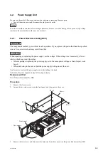
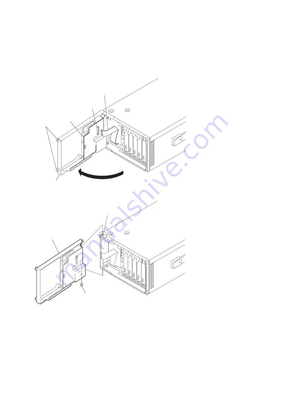
Loosen the two coin screws, and open the front panel.
2.
Disconnect the flexible flat cable from the connector CN1 on the AU-340 board.
Coin screws
Front panel
AU-340 board
CN1
Flexible flat cable
3.
Remove the step shaft, and remove the front panel from the shaft of the incom panel.
Front panel
Shaft
(Incom panel)
Step shaft
4.
Install the removed parts by reversing the steps of removal.
4-3-2.
CN-3451 Board
Preparation
1.
Open the front panel. (Refer to
“4-3-1. Removal and Installation of Front Panel”
Procedure
1.
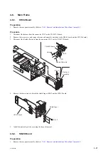
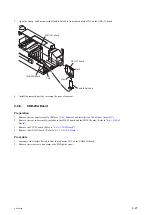
Disconnect the harness from the connector CN2 on the CN-3451 board.
HDCU2500
4-13
Содержание 10001
Страница 6: ......
Страница 12: ......
Страница 14: ......
Страница 25: ...1 5 Outside Dimensions HD CAMERA CONTROL UNIT 1 5 200 1 3 7 1 4 7 2 1 9 Unit mm HDCU2500 1 11 ...
Страница 118: ......
Страница 130: ...Harness BOARD1 and Harness BOARD2 Upper Side Harness BOARD1 Harness BOARD2 Lead pin RE 274 board HDCU2500 4 12 ...
Страница 148: ......
Страница 161: ...B 1000 7 mVp p 75 Ω termination EN 159A 159B board Side A A B C D E F G H J 1 2 3 4 5 RV305 B A NTSC PAL HDCU2500 5 13 ...
Страница 162: ......
Страница 264: ......
Страница 357: ...Section 9 Board Layouts ADO 12 CN1 CN2 CN5 A SIDE SUFFIX 11 ADO 12 B SIDE SUFFIX 11 ADO 12 HDCU2500 9 1 ...
Страница 368: ...EN 159A EN 159B The location is described at the end in this section A SIDE SUFFIX 11 EN 159B EN 159A HDCU2500 9 12 ...
Страница 369: ... B SIDE SUFFIX 11 EN 159B EN 159A HDCU2500 9 13 ...
Страница 374: ...PS 778D00 B SIDE SUFFIX 11 HDCU2500 9 18 ...
Страница 392: ...HDCU2500 SY HDCU2500 CE J E 9 968 889 01 Sony Corporation Printed in Japan 2012 1 08 2012 ...


